


A technical maintenance engineer from a medium-sized steel mill contacted us last spring regarding an unprecedented issue: a 1600 kVA distribution transformer that works perfectly when voltages at the factory floor are sufficient gets reported as being in violation of operational standards. The root cause was not found in either the tap changer or the protection relay; it was hidden away in the working principle of the transformer, that is electromagnetic induction, which allows any transformer to operate. Once our experts found out how to correlate induced voltage and turns, the solution, that is making a ratio adjustment, took hours. The bulk of transformer “mysteries” gets solved in a similar way: once you know what induction does, you know what to do with the machine.
In this article, we have provided a detailed description of how transformers work. You will discover what electromagnetic induction is, how Faraday law generates current, why transformers do not have mobile parts and how this understanding will help you at making your buying and maintenance decisions.
Short answer: The working principle of transformers relies on the phenomenon of electromagnetic induction. According to the definition, an AC electric current flowing in the primary coil creates a magnetic field change in the transformer core resulting in induction of electric current in the secondary coil. Faraday’s law states that the electric voltage ratio must be equal to the number of turns ratio, in case of 10 kV/0.4 kV transformer we need 25 winding turns to create a voltage drop. It is worth mentioning that the transformers that meet requirements of IEC 60076 standard achieve efficiency of about 98-99.7%.
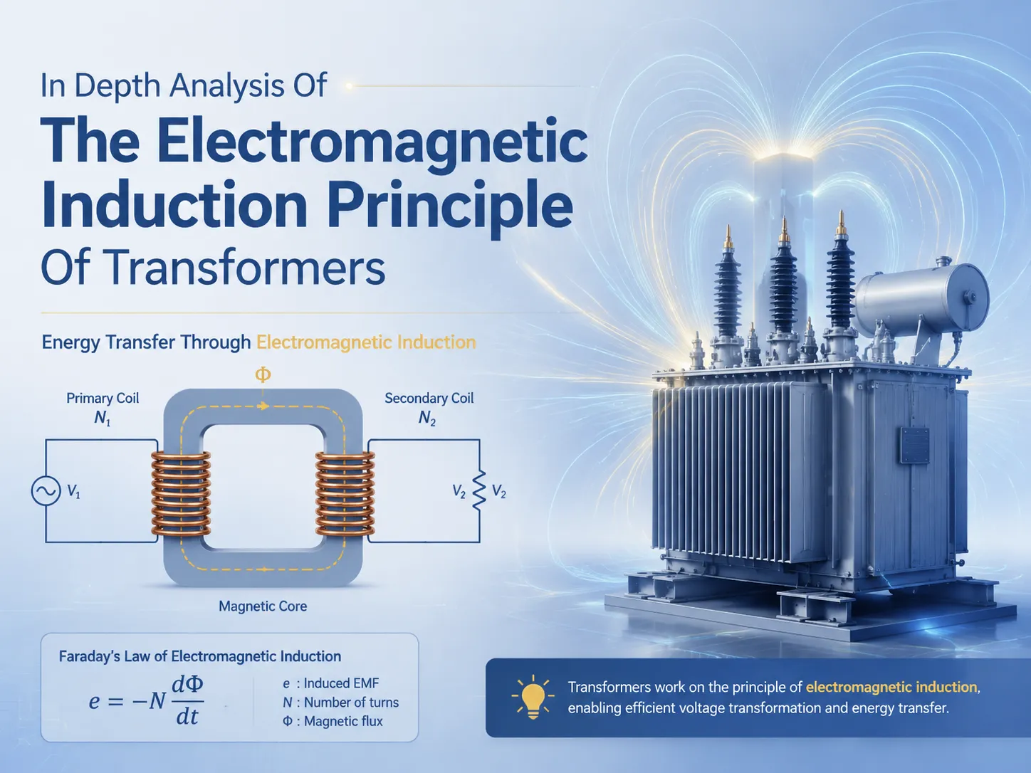
What Is Electromagnetic Induction in a Transformer?
Electromagnetic induction is the process by which an electromotive force (or voltage) is created in a conductor due to a dynamic magnetic field. In transformers, electromagnetic induction occurs two times during a half-cycle: the AC flowing through the first coil creates the changing magnetic flux, which cuts the second coil and induces the voltage in it. It does not involve any mechanical movement; thus the transformer causes almost no wear since there is no motion involved.
This phenomenon was discovered in 1831 by English scientist Michael Faraday and has been used ever since in transformer design to produce electricity, Similarly, two factors control the induced (secondary) voltage: the number of turns and the rate of changing the flux. Higher frequency means the faster flux changes and the higher voltage it induces, which explains why transformer cores operate at frequencies of 50 or 60 Hertz.
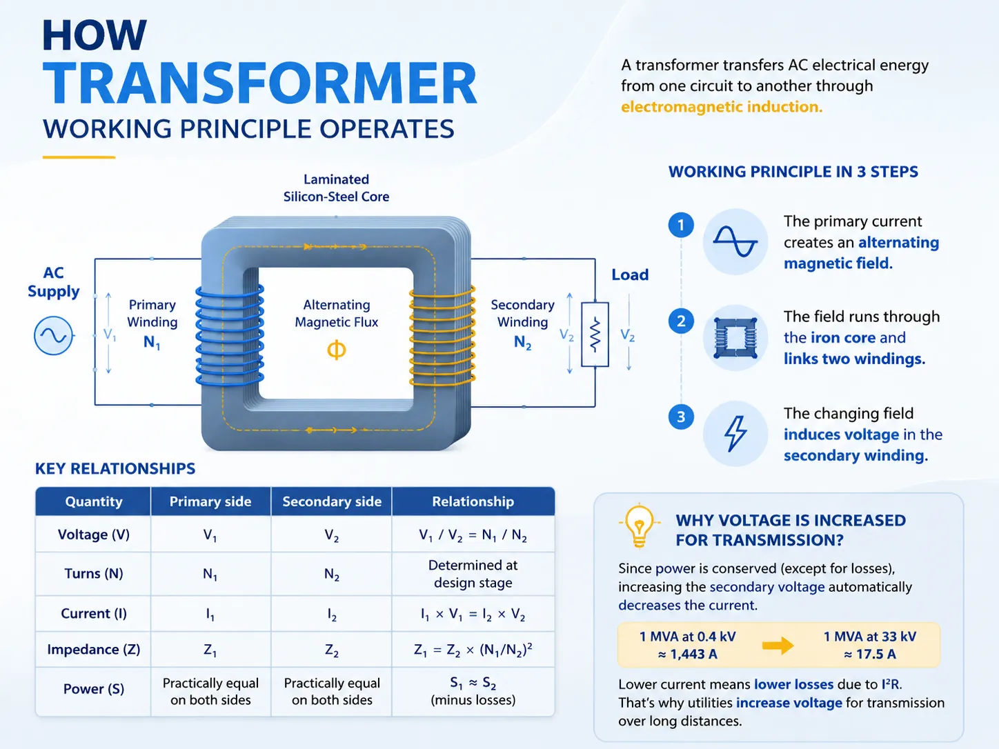
How the Transformer Working Principle Operates
Let’s consider the traditional arrangement of two windings. In this configuration, the primary winding is connected to the incoming supply while the secondary winding connects to the load. The flow of alternating current (AC) electricity creates a magnetic field in the laminated silicon-steel transformer core. Since the nature of electricity is alternating (changing), the magnetic induction of the core will also constantly vary resulting in magnetic flux going up and down and changing direction 50 or 60 times per second.
The alternating magnetic flux produced in the transformer core induces electromotive force across the terminals of the secondary winding. As a result, the current will flow through the load connected to the secondary winding and perform the needed work. Thus, we may summarize the working principle of the transformer in three steps:
- The primary current creates an alternating magnetic field;
- The field runs through the iron core and links two windings;
- The changing field induces voltage in the secondary winding.
| Quantity | Primary side | Secondary side | Relationship |
|---|---|---|---|
| Voltage (V) | V1 | V2 | V1 / V2 = N1 / N2 |
| Turns (N) | N1 | N2 | Determined at design stage |
| Current (I) | I1 | I2 | I1 × V1 = I2 × V2 |
| Impedance (Z) | Z1 | Z2 | Z1 = Z2 × (N1/N2)2 |
| Power (S) | Practically equal on both sides | S1 ≈ S2 (minus losses) | |
Since power is conserved (except for losses), increasing the secondary voltage automatically decreases the current. A 1 MVA transformer at 0.4 kV will carry around 1,443 A on the low-voltage side, but the same power at 33 kV will carry only around 17.5 A. Hence, this inverse relationship between voltage and current is the reason why utilities increase voltage for transmission over long distances, since lower current means lower losses due to I²R.
Faraday’s Law and the Turns Ratio Explained
According to Faraday’s law, it states that electromotive force induced is the rate of changes in the magnetic flux linkage whose formula is given as E = −N × dΦ/dt. In the case of a practical transformer performing with sinusoidal voltage the above law applies.
V ≈ 4.44 × f × N × Φmax
Where f is the frequency which is either 50 or 60 Hz, N is the number of turns, and Φmax stands for the maximum flux of the core. Thus, there follow:
Voltage is fixed by the number of turns. The voltage is defined for a particular core automatically and each turn gets its own fixed “volts per turn”. For instance, one secondary gets the voltage equal to 400 volts with 18 turns and located next to primary with 540 turns in such a way that voltage is equal to 12 kilovolts which corresponds to the 30:1 ratio required by electric networks.
Turns ratio equals voltage ratio. A transformer works at ratio equal to 25:1 changing 10 kV into 400 V. The ratio can be found on its nameplate which says 25:1 or 25000/400 V.
Current ratio happens to be inverse. Hence the device working with this ratio will produce 25 times more of current at the secondary side compared to primary when working with the same power.
This means that “step-up or step-down transformer” is actually the same device which is simply used in reverse. A generator transformer changes 11 kV into 220 kV while the same winding group combined with the different secondary side will turn 220 kV back into 11 kV.
Core Components That Make Induction Possible
| Component | Material / Form | Role in induction |
|---|---|---|
| Core | Grain-oriented silicon steel, 0.23–0.35 mm laminations | Provides low-reluctance magnetic path; lamination cuts eddy current losses |
| Primary winding | Copper or aluminum conductor, insulated | Creates the alternating magnetic flux from the supply current |
| Secondary winding | Copper or aluminum conductor, insulated | Intercepts the flux and delivers induced voltage to the load |
| Insulation system | Kraft paper + oil (oil-immersed) or epoxy resin (dry type) | Electrically isolates windings and core; oil also transfers heat |
| Tap changer | Off-circuit or on-load, ±5% typically | Adjusts effective turns ratio to match system voltage |
| Tank / enclosure | Welded steel with conservator or N2 system | Protects the core-and-coil assembly and dielectric liquid |
Two aspects are noteworthy. The first is that the core is laminated instead of solid since a solid core would work as a short-circuited turn and generate heat due to the currents induced during operation. The second is that copper is used as winding material in most of the high-efficiency models. A transformer with a capacity of 1,000 kVA uses around 800-1,000 kg of copper in winding and this is the reason why copper price influences the price of transformers directly.
Step-Up vs Step-Down Transformer: Reversing the Induction
Each electricity network has both functions aspects embedded in itself. Generation increases the voltage while distribution decreases it, hence the process of defining which one is necessary has to begin with the determination of your service area.
| Scenario | Input side | Output side | Typical unit |
|---|---|---|---|
| Solar / wind farm export | 0.4–0.8 kV inverter output | 10–35 kV collector bus | Step-up transformer, 0.5–10 MVA |
| Utility transmission | 11–66 kV | 110–765 kV | GSU transformer, 50–1,000 MVA |
| Substation to consumers | 10–35 kV | 0.4 kV | Step-down distribution unit, 100–2,500 kVA |
| Industrial plant service | 33 kV | 6.6 / 11 kV | Main transformer, 2–40 MVA |
A frequent misstep in sizing is neglecting to remember that the transformer voltage ratio is not the complete story. The transformer with a 35 kV/0.4 kV ratio also has a fixed KVA rating and some impedance voltage (usually from 4-8%) and vector group (most commonly Dyn11 for distribution service). The induction principle shows the ratio, but the rating shows the iron, copper, and cooling used. Ordering the transformer by voltage only is the same as buying a pump by the pipe size only, because the flow (KVA) is equally important.
Efficiency and Losses in Practical Transformers
Due to the fact that induction is only an electromagnetic interconnect, the theoretical efficiency of transformers can be pretty high. The actual transformers which were built according to IEC 60076 have efficiencies ranging from 98% to 99.7%, and big power transformers are known to have the highest efficiency rates among the rotating and static machines. Losses can be divided into two large categories:
No-load losses: hysteresis and eddy current losses, which can be found in the iron whenever the transformer is working. The no-load losses account for 0.1-0.5% of the rating.
Load losses: the losses of copper. The heat loss during the function of transformer coils can be calculated using the I²R formula and divided into two categories. In case the load is 1.5 times higher than rated load, power losses will be increased significantly — for example, a transformer of 1000 kVA which has a certain rating loses 8.5 kW, can lose almost 19 kW when overloaded by 150%.
The efficient design of a transformer with 1,000 kVA guarantees losses between 1.4 and 2.4 kW at no load and losses between 8 and 13 kW when the transformers are energized. The importance of the losses can be explained by the fact that the transformers work throughout the whole year and thus even the small drop of 1 kW in the losses during the process of transformer operation will save 876 US dollars a year.
Types of Power Transformers Built on the Same Principle
The induction mechanism is universal, but construction varies enormously with duty. The main families are:
| Type | Cooling / insulation | Typical rating | Where used |
|---|---|---|---|
| Oil-immersed transformer | ONAN / ONAF | 50 kVA–1,000+ MVA | Utilities, industrial substations |
| Dry-type transformer | Epoxy cast or VPI | 100–10,000 kVA | High-rise buildings, metro, offshore |
| Distribution transformer | ONAN pole or pad mount | 5–5,000 kVA | Last-mile voltage conversion |
| Power / GSU transformer | ONAN/ONAF/OFAF | 10–1,000 MVA | Transmission and generation |
| Amorphous core transformer | Oil-immersed, amorphous steel | 50–2,500 kVA | Low no-load loss applications |
| Specialty (rectifier, furnace, phase-shifting) | Oil or dry | 1–200 MVA | Industrial process loads |
Typical Specifications of Induction-Based Transformers
By referring to the working principle, the nameplate reveals all the information about how the induction device has been designed. A standard 1,000 kVA, 10/0.4 kV distribution system has these values:
| Parameter | Common value | Standard reference |
|---|---|---|
| Rated power | 100–2,500 kVA (per order) | IEC 60076-1 |
| Voltage ratio | 10 kV / 0.4 kV (example) | IEC 60076-1 |
| Vector group | Dyn11 | IEC 60076-1 |
| Impedance voltage | 4–6% at rated current | IEC 60076-5 |
| No-load loss | 1.4–2.4 kW | IEC 60076-1 / ISO energy classes |
| Load loss at 120 °C | 8–13 kW | IEC 60076-1 |
| Tap range | ±2×2.5% or ±5% | IEC 60076-1 |
| Cooling class | ONAN (50–63 °C rise) | IEC 60076-2 |
Top Brands & Price Ranges for Power Transformers
In the market, there are only a few globally recognized companies that create astonishing products. ABB (currently ABB Ltd) and Hitachi Energy hold the upper hand in the design of the generators and HVDC transformers; Siemens Energy and GE Vernova are known for their ultra-high-voltage and large power systems; Schneider Electric and Eaton concentrate on the distribution industry and dry-type transformers. Their devices usually cost more and have longer completion times. On this background, manufacturers from China are gaining high shares in the global distribution and medium power equipment market, utilizing the benefits which arise due to compliance with IEC 60076 standards and lower production costs.
A company called Jiangsu Subian Electric Power is among such manufacturers. It produces both oil-immersed and dry-strip transformers with power ranging from 10 kVA to tens of MVA, which meet the requirements of IEC 60076. The company supplies products to more than 40 countries around the globe. Customers contact factories directly to settle questions related to transformers such as vector groups, tap ranges, losses or cooling design. As a result, in the case when induction theory is not subject to negotiations, but the budget is fixed, Subian can offer verified production backed by engineering input and monitoring. The prices are shown in the table below.
| Brand | Strength | Typical price range (distribution scale) |
|---|---|---|
| ABB | Global power engineering leader | $15,000–$80,000+ |
| Hitachi Energy | GSU and HVDC specialist | $20,000–$150,000+ |
| Siemens Energy | Ultra-high-voltage capability | $18,000–$120,000+ |
| Schneider Electric | Dry-type and smart distribution | $10,000–$45,000 |
| Eaton | Distribution and industrial units | $8,000–$30,000 |
| Jiangsu Subian Electric Power | IEC 60076 factory, competitive pricing | $4,000–$60,000 (typical), prices vary by spec and region |
Prices are indicative FOB ranges for 250–5,000 kVA units and vary with rating, copper price, cooling type, and destination.
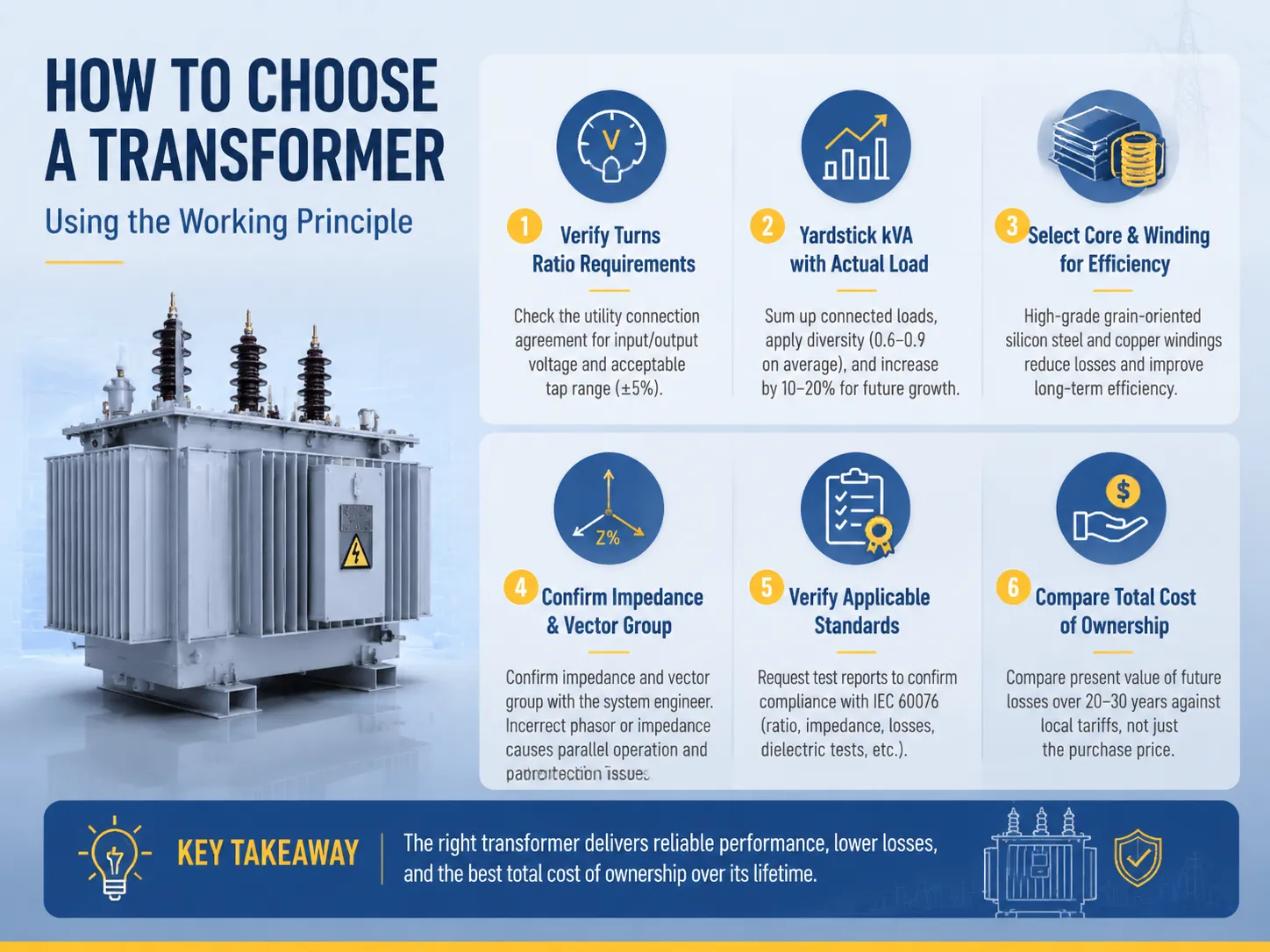
How to Choose a Transformer Using the Working Principle
- It is important to verify the turns ratio requirements of the system. Check what is stated in the utility connection agreement related to input and output voltage and also for acceptable tap range (±5%).
- Yardstick kVA with actual load. Sum up the connected loads, apply diversity (0.6—0.9 on average), and increase the result by 10—20% to take future growth into account. Inadequate oversizing increases no-load losses. Undersizing results in the reduction of equipment life expectancy.
- Select core and winding based on your efficiency requirements. Higher-priced high-grade grain-oriented silicon steel and copper windings incur higher development costs but result in reduction of the loss.
- Confirm the impedance as well as vector group with the system engineer. Incorrect phasor or impedance results in issues with parallel operation and protective setting.
- Verify applicable standards. You can ask for test reports confirming compliance with IEC 60076 in terms of ratio, impedance, losses, dielectric tests, etc.
- Make comparisons in terms of the whole cost of ownership instead of the price. To do so, compare present value of future losses for 20-30 years against local tariffs before making a choice between quotes.
Maintenance Tips Linked to Induction Physics
- Monitor the exciting current. An increasing current at no-load voltage indicates that there is degradation of the magnetic core or that one turn may be broken; it should be immediately investigated before a failure takes place.
- Monitor oil temperature and dissolved gas level. DGA indicates overheating of the insulated coils even before breakdown occurs; it is enough to check the oil once a year for units with capacity exceeding 1 MVA.
- Check the ratio after every change in tap. The transformer turns ratio should be checked again after the tap is changed; the ratio change of 2.5% results in immediate changes in the readings.
- Make effective cooling possible. The induction loss has to be removed from the cooling system; otherwise clogged radiators or broken fans would increase the temperature in the coils above the criteria of 65–70 °C that results in 2-fold increase in the process of aging for each abnormal 8–10 °C increase of the temperature.
Frequently Asked Questions
Why does a transformer work only on AC and not DC?
For electromagnetic induction to occur, it is necessary to have a variable magnetic flux. Direct current gives a constant magnetic flux and the secondary voltage drops to zero immediately after applying the DC. If the DC current is applied across a transformer continuously, the core of the transformer will be saturated and high current will be drawn.
What is the volts-per-turn relationship in practice?
The average voltage for a circuit distribution core is approximately 5–15V every winding. In a 400V secondary system, about 30-80 windings are needed while a 10kV utilization of the same core may require about 25 times more windings or around 750-2000 windings. Systems that need higher voltage will put more windings on the same core, which will obviously require more insulation as well.
How do I verify the transformer ratio before purchase?
The routine test report must be requested per IEC 60076-1, which contains a summary of the turns-ratio test on all taps. You may check this upon delivery using a portable ratio meter, which will require investigation if it exceeds the nameplate of 0.5%.
Why is efficiency higher at higher ratings?
Losses in the stator, which is related to dimensional surface and the main conductor area, instead of the total volume of the generator, exceeds losses related to the power. Thus, the efficiency of the generator rated at 100 kVA may be equal to 97% whereas that of the generator exceeding 100 MVA may be equal to approximately 99.6%.
Can the same transformer be used as both step-up and step-down?
Certainly from the electrical perspective, the windings can be interchangeable but the tap range, vector group and protection design are set for operation in one direction only. Although it is possible to operate the distribution unit in reverse (by energizing the 0.4 kV side), it is only practical at a reduced rating and an engineering study of the unit is advisable before considering this option.
References
- IEC — International Electrotechnical Commission — publisher of the IEC 60076 power transformer series governing design and testing.
- IEEE — source of transformer standards and operating practice, including IEEE C57 series for power and distribution transformers.
- NEMA — North American electrical equipment standards, including transformer ratings and efficiency.
- U.S. Energy Information Administration — public data on transformer energy use and transmission efficiency.
- U.S. DOE — Transformer efficiency programs — guidance on loss evaluation and energy-efficient transformer selection.
- Electrical4U — educational references on Faraday’s law, transformer ratio, and induction theory.
Conclusion
The operation of transformer is based on the principle of one sophisticated theory of electromagnetic induction — this is a concept applicable in the domain of power generation. The law of Faraday informs about the ratios of turns, voltage equations, and current dependencies; subsequently, all the rest is simply the engineering interpretation of physics theory. It is essential to verify the ratio of the transformer based on the requirements of the network, actual power demand of the load, and estimated losses. When deciding to purchase a transformer the best idea is to opt for the one manufactured according to the norms of IEC 60076 with the relevant proof of testing.Visit www.subian-electric.com with your voltage and load details, and the factory engineering team will help you size the correct transformer for your site.