


The short answer is that the majority of charging stations require one distribution transformer, which can be classified as medium-to-low voltaged transformer, and designed according to the actual coincident loads of the chargers – not their nameplate rating, harmonics-heavy supplies operation for several hours throughout the day and supply conditions specific to the site. This usually refers to a pad-mounted transformer in an open parking lot, to a cast resin type transformer in a man-made structure or underground garage, to a prefabricated substation in a large charging station/ bus depot, along with a set of additional current transformers which are preserving the supply but usually are not attracting attention until the time comes to place an order for any meters or protective relays.
This guide is for developers, EPC contractors and electrical consultants who are responsible for putting transformer for an EV charging station into a specification. It includes the information about the transformer types and ratings, harmonics, to show the examples of sizing, to discuss current transformers and to provide a checklist for the suppliers. If you are still at the grid-planning stage, our companion articles explain what the DOE study says about transformer and feeder upgrades and what the 2025 EV charging market report reveals about transformer demand.
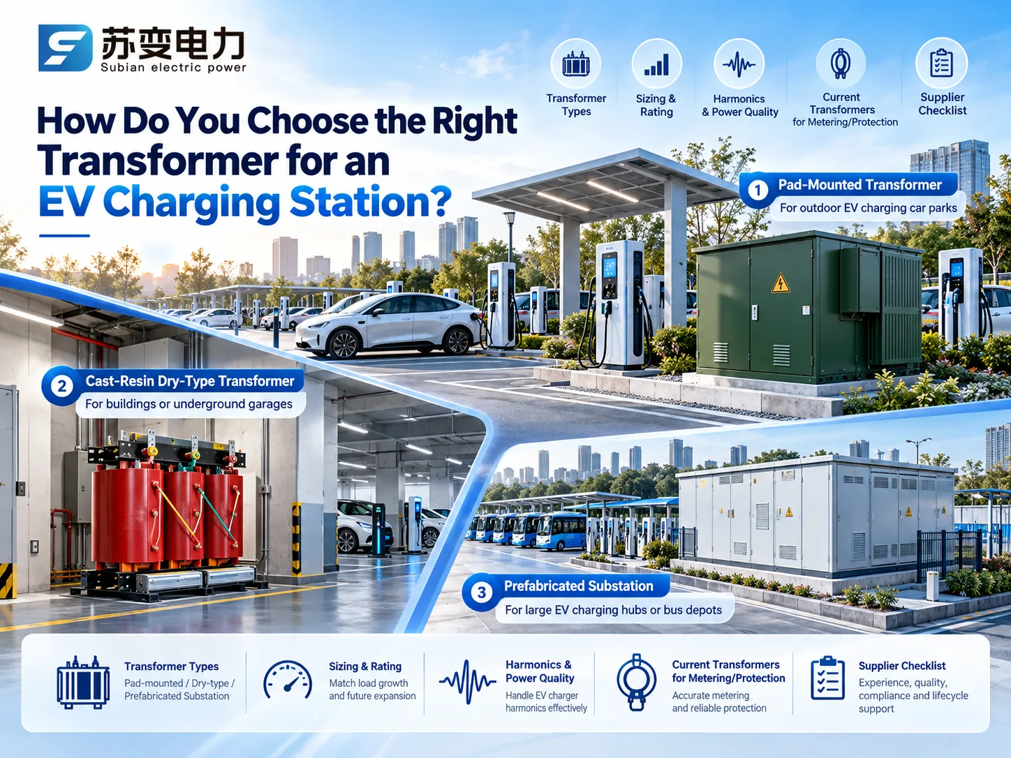
Which Transformers Sit Between the Grid and an EV Charger?
The main acquisition refers to the transformer that reduces the utility voltage supply of 10 to 35 kV to charger voltage. In IEC countries, in most cases, the transformer voltage is 400/230 V at 50 Hz, which most DC or AC chargers are able to accept directly. In North America, sometimes a very low voltage transformer will be used to convert 480 V into 208Y/120 V for Level 2 chargers. The rest of this guide therefore focuses on the site transformer, as this is the high-value, long-lead item that makes or breaks a site energisation.
Matching the Transformer Type to the Charging Site
The physical form of an EV charging station transformer is decided by where it will stand, how much power the site draws and who needs access to it. The table below gives the usual starting point.
| Site | Typical demand | Usual transformer form | Why |
|---|---|---|---|
| Rural forecourt or small car park with a few AC points | Under 150 kVA | Pole-mounted or small pad-mounted oil unit | Lowest cost where an overhead line is already present |
| Supermarket, hotel or office car park with mixed AC and DC | 250 to 1,000 kVA | Three-phase pad-mounted transformer | Compact, tamper-resistant, installs on a concrete pad next to the chargers |
| Underground garage, multi-storey car park or building basement | 250 to 2,500 kVA | Cast-resin dry-type transformer in an enclosure | No oil, self-extinguishing insulation and easier fire approval indoors |
| Highway fast-charging hub | 1 to 5 MVA | Prefabricated substation with MV switchgear, one or two transformers and an LV board | Delivered as one tested unit, which shortens site work |
| Bus or truck depot, often with solar and storage | 2 to 10 MVA or more | Several transformers in prefabricated substations, sometimes a 33 kV connection | Redundancy and room to add charger capacity in stages |
Pad-Mounted Transformers for Open Car Parks
A pad-mounted transformer includes the transformer equipment, the medium-voltage connections and the low-voltage connections in a locked enclosure. The device can be sited at the edge of the car park, near the chargers, reducing the amount of low-voltage cable needed. A DC charger with a power of 120kW uses about 186A at 400 V, therefore every meter of cable between the transformer and the charging stations adds to the cost of copper. Subian builds three-phase pad-mounted transformers configured to the project network voltage, vector group and standard.
Dry-Type Transformers for Garages and Buildings
Firefighters and insurance companies are wary of oil-based apparatuses in closed parking lots. A dry-type transformer made of cast resin circumvents the oil sump, fire safety wall, and enough checking protocol that appears to be necessary for oil-based devices, trading it off for a tad bit steeper price and a requirement for a designed clean, ventilated space.Subian’s dry-type transformer range includes the 6 to 10 kV SCB series epoxy resin cast units commonly used in building substations. For a broader comparison, see our guide to dry-type versus oil-immersed transformers.
Prefabricated Substations for Hubs and Depots
In cases where a site requires both its own MV switchgear and at least two transformers, a factory-built substation is usually the quickest option available. The ring main unit, transformer and LV board come in pre-wired and type-tested, leaving only the tasks of building a foundation, pulling cable, and commissioning on site. Subian’s YB series prefabricated substation and ZGS series combined substation cover this role, and our compact substation guide explains how to specify one. As our 2025 EV charging market report shows, average public charger power keeps rising, so it pays to leave space in the layout for a second transformer.
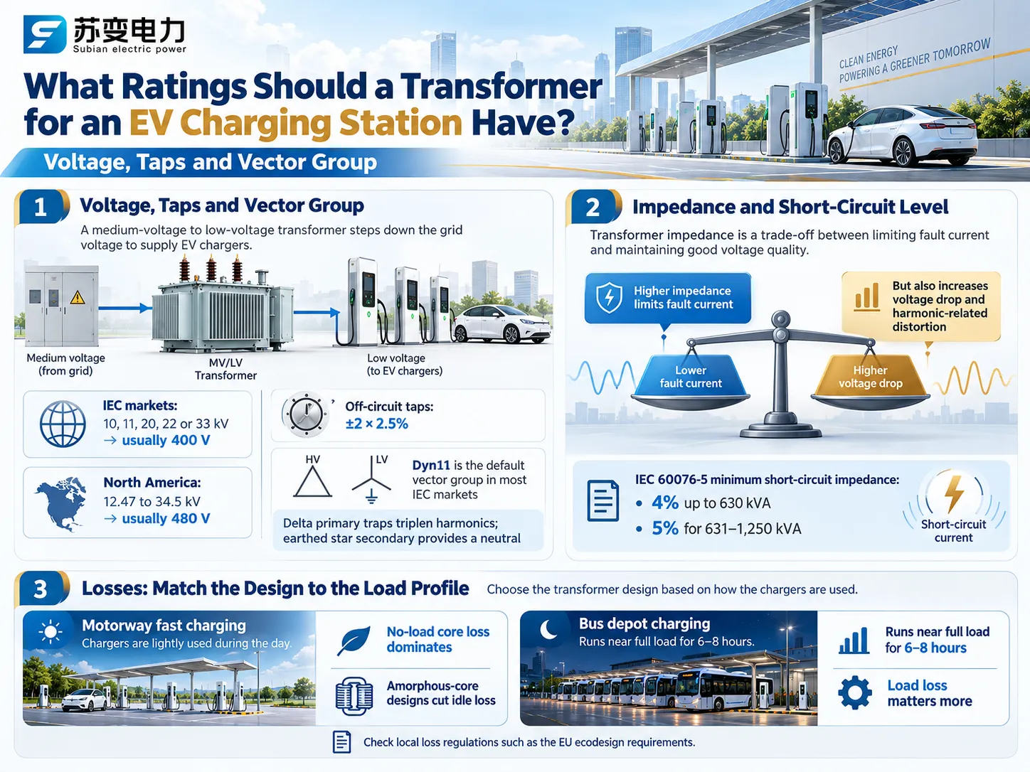
What Ratings Should a Transformer for an EV Charging Station Have?
Voltage, Taps and Vector Group
In the case of primary supplying voltages, it’s expected to match the voltage levels of the connected local electric grid and that means it’s either 10 to 33 kV as per IEC specs or 12.4 to 34.5 kV in North America. The secondary should match charger input and typically has a voltage rating of 400 V for IEC specifications and 480 V for North America. A non-load tap changer can cope with the problem of the wrong primary supply voltage, however, checking the charger specs is required since some chargers experience a decrease in performance when the input voltage is lower than expected.
For DC fast charging applications, Dyn11 is the commonly used vector group throughout the whole IEC standard countries. Our article on how a delta-wye transformer works covers the basics.
Impedance and Short-Circuit Level
The impedance is a compromise. Its high value reduces the fault current flowing through the low-voltage switchgear and keeps the self-protection of the chargers within their limits; on the other hand, it increases the voltage drop and causes greater harmonic transformer’s voltage distortion. According to IEC 60076-5, the minimum short circuit impedance for transformers with power ratings of less than 630 is 4 percent, while for those rated between 631 and 1250 kVA is 5 percent, which is the case for most transformer manufacturers.
Losses: Match the Design to the Load Profile
Public fast chargers on a motorway may sit idle for much of the day, so the no-load core loss that flows around the clock dominates the energy bill. An amorphous-core design, such as Subian’s 10 kV SCBH series amorphous alloy dry-type transformer, cuts that idle loss sharply. A bus depot is the opposite: the transformer runs near full load for six to eight hours every night, so load loss matters more. Tell the supplier which pattern your site follows, and check local loss regulations such as the EU ecodesign requirements for distribution transformers.
Harmonics and K-Factor: The Aspect That Is Overlooked in Most of the Specifications
All of the EV chargers are responsible for the conversion of the AC current to DC, thereby operating as a non-linear type of load. Simple six-pulse diode rectifiers are responsible for producing an AC current containing harmonics of the 5th, 7th, 11th, and 13th numbers. Most of the modern high-power chargers make use of the active front end or the Vienna rectifier. In order to prove the effective capability of the Vienna rectifier, an IEEE Access article indicated that input current distortion could be less than 3.3% and stay lower than the common 5% requirement as indicated in IEEE 519.
The rise of the harmonic currents will lead to the increase of the eddy currents and stray losses, which will mean that transformer will function in warmer conditions than expected, based on its kVA loading. IEEE C57.110 is responsible for providing an algorithm for measuring derating based on one or another harmonic spectrum. In the USA, dry types of transformers could be found under K-type markings depending on the K-factor presented (UL 1561). Some manufacturers recommend K-9 type of the transformers for Level 1 and Level 2 chargers and K-4 for cases when the scope of the EV load is relatively small. There are no practices where K-factor rating practices are applied, therefore it would be wiser to provide the manufacturer with the expected harmonic current spectrum.
| Charger front end | Dominant harmonic orders | Typical current THD | What it means for the transformer |
|---|---|---|---|
| Six-pulse diode rectifier | 5th, 7th, 11th, 13th | High; usually exceeds IEEE 519 and IEC limits without mitigation | Derate per IEEE C57.110, specify a K-rated unit, or add filtering |
| Twelve-pulse rectifier | 11th, 13th, 23rd, 25th | Much lower than six-pulse, with the 5th and 7th largely cancelled | Moderate extra loss; usually covered by a modest margin |
| Active front end or Vienna rectifier | Low-level, higher orders | Usually below 5 percent at rated load | Standard design is generally adequate; confirm with charger data |
Two techniques that can be implemented in order to minimize the problem are phase shifting and making a full installation assessment. Phase shifting is about distributing chargers between two transformers or secondary windings with the angle of a phase difference equal to 30 degrees, which will help in cancelation of the 5th and 7th harmonics at the upstream level. The second techniques suggest making an assessment of the whole installation. It should be noted that IEC 61000-3-12 defines harmonic standards and sets the limits for the equipment work that exceeds 16 A and up to 75 A for each phase.
How to Size a Transformer for an EV Charging Station
Our DOE report guide works through a pure DC fast-charging hub, and the market report article sizes a bus depot. Many real projects are mixed, so here is a retail site with both AC and DC charging plus an existing building load.
Assumptions: four DC chargers of 120kW have 75 percent coincidence factor due to load management, with efficiency of 95 percent and power factor of 0.98. Twelve AC chargers of 22kW were considered with 50 percent diversity factor, since vehicles remain parked for several hours; power value of 60kVA of the existing lighting, refrigeration and workshop load; plus 20 percent of reserve for chargers and harmonic heating.
| Load | Calculation | Result |
|---|---|---|
| DC chargers | 4 × 120 kW × 0.75 ÷ 0.95 ÷ 0.98 | About 387 kVA |
| AC chargers | 12 × 22 kW × 0.50 ÷ 0.99 | About 133 kVA |
| Existing building load | As measured | 60 kVA |
| Total coincident demand | 387 + 133 + 60 | About 580 kVA |
| With 20 percent margin | 580 × 1.2 | About 696 kVA |
| Next standard size | IEC practice / North American pad-mount | 800 kVA / 750 kVA |
The requirement for virtually the same power capacity without load management requires approximately 842 kVA at the outset and 1,011 kVA at the end, which translates into approximately 1,250 kVA according to IEC specifications. Load management is crucial as it indicates two types of transformers to be ordered and hence, should be specified ahead of the transformer order placement. For the steps between ratings, see our guide to standard transformer sizes, and for the basics, what a kVA rating means.
In addition to the above specification, the depot requires one more consideration. While standard distribution transformers can be overloaded to a certain degree due to the fact that residential loads cool down overnight, a depot that charges its buses only overnight cannot benefit from such cooling periods. It is important to follow loading instructions for oil-filled transformers given in IEC 60076-7 and for dry transformers in IEC 60076-12 since it will help to determine the precise charging patterns.
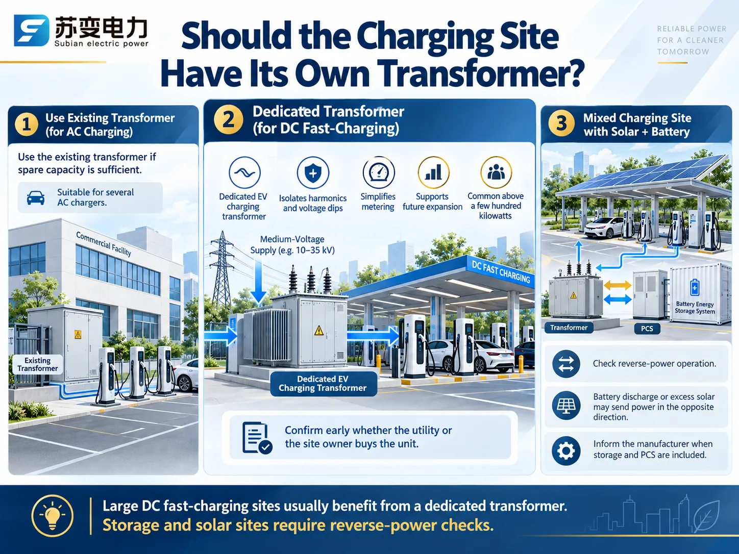
Should the Charging Site Have Its Own Transformer?
If a building has its own transformer that can supply enough electricity, several AC chargers can be connected to this supply. The U.S. multi-state grid study modelled a dedicated three-phase service transformer for every DC fast-charging site, and most utilities take the same view for anything above a few hundred kilowatts. A dedicated EV charging transformer also keeps charger harmonics and voltage dips away from other customers, simplifies metering and lets the site grow without disturbing the building supply. Confirm early whether the utility or the site owner buys the unit.
In the case of mixed charging stations equipped with solar panels or batteries another check has to be performed. The transformer may also work in opposite direction in case when a battery discharges or when the power generated by solar panel exceeds the needs of the facility. Inform the producer about the specifics of the situation so that they can take them into consideration when designing the device. The article about the energy storage compact substation will tell you how storage, PCS and transformer work together.
Switchgear and Protection Around the Transformer
- MV side: a ring main unit with a load-break switch and fuses for smaller units, or a vacuum circuit breaker with a protection relay for larger ones, such as Subian’s XGN15-12 gas-insulated ring main unit or VS1 indoor vacuum circuit breaker. Our ring main unit specification guide covers the options.
- LV side: a main breaker, an outgoing feeder for each charger or group, and surge protection. A draw-out board such as the GCS low-voltage switchgear lets individual feeders be maintained without shutting the site down.
- Residual current protection: IEC 60364-7-722 requires each charging point to be protected against DC fault current of 6 mA or more, either with a Type B RCD or with a Type A RCD plus a residual direct current detecting device complying with IEC 62955.
Which Current Transformers Does an EV Charging Station Need?
Current transformers are a separate decision from the power transformer, but they are specified at the same time. When people look for a current transformer for EV charging stations, they usually mean one of four devices, each with a different job.
| Location | CT type | Purpose | Typical specification |
|---|---|---|---|
| MV incoming panel | Indoor bar-type or ring-type CT with metering and protection cores | Revenue metering and relay protection of the transformer feeder | 5 A or 1 A secondary; class 0.2S or 0.5S metering; 5P or 10P protection |
| LV main board and charger feeders | Window or bar-type LV CT | Site sub-metering and per-charger energy monitoring | Class 0.5S or 0.2S, ratio matched to the feeder current |
| Incoming supply of a home or small site | Split-core CT clamp | Dynamic load management, so the charger throttles before the main fuse overloads | The rating and output signal the charger maker specifies |
| Inside AC chargers | mA-range residual current CT, AC and DC sensitive | Detects DC fault current of 6 mA or more, as IEC 62955 requires | Built in by the charger manufacturer |
Metering CTs: Choose an S Class
Charging load is variable, being almost zero when there are no bays used while charging to full load when all bays are operational. Metering classes as per standards will guarantee accuracy of measurement starting from 5 percent of rated current and there are classes that cover extended range so called class S as per IEC 61869-2 that can measure down to 1 percent of the rated current. For example, Class 0.2S would keep accuracy of measurement within plus/minus 0.2 percent for current between 20 and 120 percent of the rated current and 0.35 percent for 5 percent of the rated current. Choose the ratio closest to the maximum which we expect taking into account that 120 kW DC charger at 400 V takes approximately 186 A, thus using 200/5 CT would be sufficient. Transformer used in our examples is rated for 800 kVA and full load current is approximately 1155 A thus 1250/5 CT is used.
Protection CTs on the Medium-Voltage Side
On the MV side, protection cores of class 5P or 10P feed the overcurrent and earth-fault relay. A 4 MVA depot transformer at 10 kV has a full-load current of about 231 A, so a 300/5 ratio leaves room for expansion. Subian’s LSY-10 integrated three-phase current transformer combines three cores in one unit for 10 kV switchgear, with primary ratings from 100 A to 1,000 A, metering classes 0.5 and 0.2S, and protection classes 5P and 10P. For wiring practice, see our guide to current transformer connection; for earth-fault detection on MV cables, our article on the core balance current transformer; and for budgets, the cost of a current transformer. Never leave a CT secondary open while the primary is energised.
CT Clamps for Dynamic Load Management
Many residential and small business users opt to install a charger even when they do not upgrade their electrical supply. What this means is that a split-core CT clamp is attached to the incoming energy source wire right before the supply begins to divide into various circuits. The clamp’s job is to provide the total current to the charger so that it knows when to start reducing its level of charging. In case of a three-phase supply, three separate clamps should be used, one for each phase, and they should be pointing in the direction from supply to load. The clamp itself should be the one recommended by the charger manufacturer.
Why the DC Side Uses Shunts, Not CTs
Generators of current employ the principle of magnetic induction and can thus only measure alternating current. DC power is measured with a shunt or Hall effect sensor in a DC energy meter; static DC meters of classes 0.5 and 1, included in IEC 62053-41, refer to electric vehicle charging stations measuring both the AC and DC sides. DC metering only bills for the energy delivered to the vehicle, while AC metering through current transformers reflects charger losses. Therefore, it is essential to find out what your charging service billing rules indicate.
EV Charging Station Transformer Specification Checklist
| Item | What to state |
|---|---|
| Charger list | Number, rating and type of every charger, AC and DC, plus any existing site load |
| Load assumptions | Coincidence or diversity factor, load-management scheme and a daily charging profile |
| Ratings | kVA, primary and secondary voltage, frequency, tap range, vector group and impedance |
| Harmonics | Charger current THD or harmonic spectrum, and any K-factor requirement |
| Construction | Oil-immersed or dry-type, pad-mounted, kiosk or prefabricated substation, enclosure protection degree |
| Losses | Maximum no-load and load losses, or the applicable efficiency regulation |
| Current transformers | Ratio, accuracy class, burden and secondary current for each metering and protection point |
| Site and power flow | Ambient temperature, altitude, flood and corrosion risk, and whether solar, storage or vehicle-to-grid will send power back |
| Standards and documents | IEC 60076 or IEEE C57, IEC 62271-202 for prefabricated substations, IEC 61869-2 for CTs, test reports and drawings |
Frequently Asked Questions
What size transformer does an EV charging station need?
The amount of that capacity running simultaneously, among other things, is determined by the amount and rating of the chargers. From the example worked out earlier, the demand is approximately 580 kVA, consisting of 4 120 kW DC chargers and 12 22 kW AC chargers working in the load management mode, after which it becomes an 800 kVA transformer according to IEC standards after applying a 20 percent margin.
Do EV chargers need a K-factor transformer?
There are exceptions, as chargers equipped with front-end rectifiers and distortion factors below approximately 5 percent can work properly with a regular transformer. Earlier six-pulse designs also allow for a K-rated transformer for North American operations or a transformer that meets the specified harmonic spectrum in IEC markets.
What current transformer is used in an EV charging station?
There are exceptions, as chargers equipped with front-end rectifiers and distortion levels below about 5 percent can successfully operate with an ordinary transformer. Earlier six-pulse designs enable the use of a K-rated transformer for North America or any transformer compliant with the required harmonic spectrum applicable to IEC markets.
Can a current transformer measure DC charging current?
No. A CT measures only alternating current. DC output is measured with a shunt or Hall-effect sensor in a DC energy meter, typically one built to IEC 62053-41.
References
- IEEE 519-2022: Standard for Harmonic Control in Electric Power Systems
- IEC 62955: Residual direct current detecting device for mode 3 EV charging
- IEC 62053-41: Static meters for DC energy
- Harmonics (electrical power), Wikipedia
- Current transformer, Wikipedia
- Charging station, Wikipedia
Choosing a transformer for an EV charging station comes down to sizing on real demand, designing for harmonics and the daily load cycle, picking the form that fits the site, and specifying the current transformers that meter and protect it. Jiangsu Subian Electric Power Equipment Co., Ltd. designs and builds pad-mounted and dry-type transformers, prefabricated substations, new energy substations and integrated current transformers for charging hubs, car parks and fleet depots, configured to your network voltage and standard. Send your charger list, grid voltage and site conditions through our contact page, and our engineers will reply with a sizing check, drawings and a factory quotation.