


When consulted, engineers could mention relays, circuit breakers, or current transformers (CTs) to discuss how protection against ground fault is carried out. However, the actual decision about the strength of the fault and whether the entire facility shuts down or only one feeder is made by a resistor. Neutral earthing resistor (NER) is considered to be one of the most critical components related to medium voltage (MV) systems, however, there is little information about it for people outside electrical engineering. This article covers what is NER, how it functions, its parts, how to choose NERs, and how much it costs.
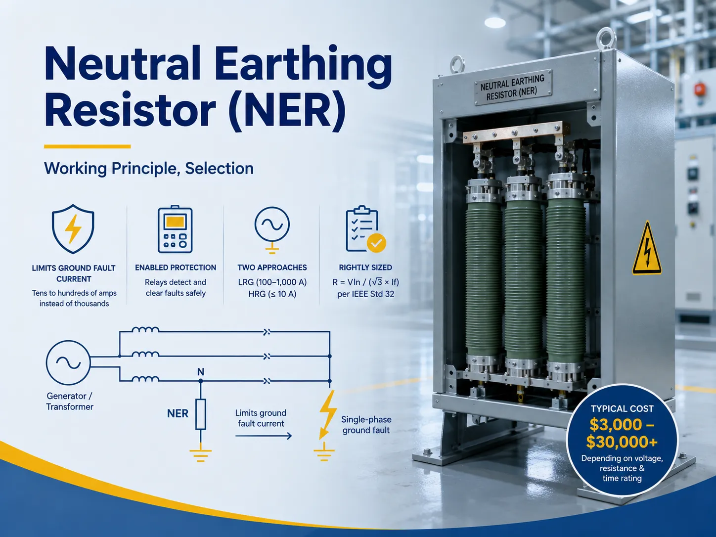
Quick answer: NER/NGR or Neutral earthing resistor means a resistor that connects the neutral of the generator or transformer to the ground. This gadget is meant to restrict the single-phase short circuit earth fault current within limits which are acceptable and manageable i.e. in the range of tens or hundreds of amps rather than thousands.
What Is a Neutral Earthing Resistor?
A neutral earthing resistor is just what it sounds like: a resistor connected between a generator’s or transformer’s neutrality point and the ground in those systems which have neutral conductors (wye-connected windings). It is an element inserted into the circuit for ground fault current flow limiting in cases when one of the phases gets on the ground. The amount of the limited current is large enough for the relay to react on it and small enough not to damage power cables or affect people.
The neutral earthing resistor occupies an intermediate position as compared to two extremes, namely, solidly earthed systems (where fault currents from the ground fault may reach thousands of Amperes) and ungrounded systems (without the intentional earthed neutral and, therefore, invisible ground fault). A neutral earthing resistor makes one be able to control the flow of the ground fault current, detectable faults and overvoltage transients.
The broader grounding picture — why and how transformer neutrals are grounded — is covered in our transformer grounding basics article; the NER is the component that makes a specific grounding philosophy work.
How It Works
Consider the situation when there is a phase C-to-ground fault in transformer connected in Y-formation. The path of fault current consists of: the fault point, the ground, NER, neutral of transformer, and phase C winding. There is a resistor in the NER and, according to Ohm’s law, the solution is evident.
According to the appropriate formula (indeed IEEE Std 32): R = Vln / (√3 × If) ,where Vln represents system line voltages between phases and If refers to the desired value of ground fault current. In other words, if we take for calculation the case of the 6kV system with the resistive connector having a resistance of 10 Ohm, failure current drops from 1000 A effectively grounded system to about 346 A, which is still sufficient to trip the relay but low enough to allow cables, switchgear, and the fault area to be recoverable despite the damage.
There are three things happening simultaneously during a fault event. The current is limited by the resistor, voltages are determined by the proper NER unit allowing the protection relay to detect the fault properly, and the fault energy is dissipated in the resistor in the form of heat, which proves the fact that NER are only rated for short time but not in continuous operation.
Types of NER
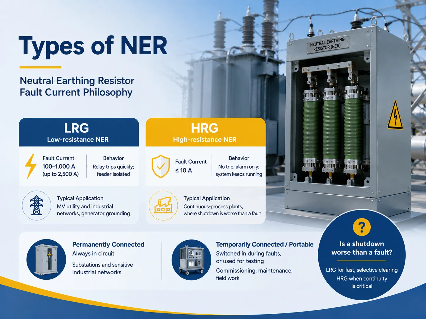
NERs are classified depending on the amount of fault current they permit, and the choice of NER type is one driven by the protection philosophy rather than cost:
| Type | Fault Current | Behavior on Fault | Typical Application |
|---|---|---|---|
| Low-resistance NER (LRG) | 100-1,000A (some designs to 2,500A) | Relay trips quickly; feeder isolated | MV utility and industrial networks, generator grounding |
| High-resistance NER (HRG) | ≤10A | No trip; alarm only; system keeps running | Continuous-process plants, where shutdown is worse than a fault |
| Permanently connected | — | Always in circuit | Substations and sensitive industrial networks |
| Temporarily connected / portable | — | Switched in during faults, or used for testing | Commissioning, maintenance, field work |
In making a decision between LRG and HRG the question to be answered is whether shutdown is worse than fault. If a utility feeder can afford a short interruption it will opt for LRG which is fast and selective. If a chemical plant is involved with activities where an unplanned shutdown might result in material solidification then HRG will be chosen to allow for fault to be acknowledged while the facility prepares for an orderly shutdown. For the protection coordination around these choices, our earth fault protection basics article shows how the resistor value and the relay settings work together.
Components and Construction
A modern NER system comprises more than just a resistor element packed in an enclosure. Here is what a typical unit consists of:
- The resistive elements: stainless steel (304/316/316L) grids for most cases, nickel-chromium alloy (Cr20Ni80) for challenging areas or iron-chromium-aluminum (FeCrAl) for economical designs. Stainless steel elements are capable of working under short-term modes at no higher than 760ºC (IEEE 32) and ≤385ºC under continuous operation.
- Insulation system: the system must meet the voltage requirements and be effective at both power frequency withstand and basic impulse level (BIL) in relation to the network characteristics (for example, a NER of 10 kV should be able to withstand 42 kV at power frequency and 75 kV impulse).
- Enclosure: IP20/IP23 for indoor and IP54/IP55 with louvered ventilation for outdoor use.
- Monitoring devices: including a current transformer for fault current measurement, an isolator or vacuum contactor for disconnecting the NER and an NGR monitoring device with open circuit resistance, temperature PT100, and event recorders.
When you buy an NER, the current transformer inside is a small but critical part — it is what the relay reads, and the current transformer product range explains the CT family and its ratings.
The Symbol and Circuit Position
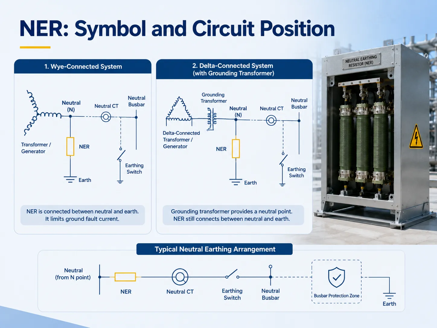
In one-line diagrams, the neutral earthing resistor (NER) is represented by the resistor notation (either rectangle or zigzag) connecting one terminal with the neutral point of either the transformer or the generator and the other terminal with the earthing symbol (the three lines triangular shape). In these cases when the neutral point is not there (delta connection), a grounding transformer is used to create the neutral point; afterward, the NER is connected to that neutral. In every case, the resistor is always connected between the neutral point and earth and never in series with the phase conductors.
If one looks at drawings of transformer projects or generators, the NER can be found on the neutral earthing diagram along with the neutral current transformer (CT), earthing switch, and neutral busbar protection, making it prove the grounding concept at once.
How to Size and Select an NER
Choosing the right unit is a six-step process, omitting any of which can either jeopardize safety or lead to hefty costs:
- Rated voltage — the voltage measured from earth to phase in the system (Vln), as well as impulse withstanding voltage matching the requirements of the installation.
- Fault current target (If) must be higher than the capacitive charging current of the system (to avoid arcing or resonance overvoltage) yet lower than the limits of cable and equipment thermal capacity, while still being considerably above the relay activation (not less than 10A).
- Resistance value = R = Vln / (√3 × If).
- Time rating = 10s-30s for LRG, continuous when it comes to HRG and leading to determination of thermal design and I²t energy rating (e.g., capable of withstanding 400 kA²s at 10kA/0.4s).
- Material of the elements = stainless steel for general applications, nickel-chromium alloys for use in coastal regions.
- Enclosure and monitoring = whether it is going to be indoor or outdoor, and value of the CT and monitoring units integrated (IP degree of protection).
Additionally, there is a practical recommendation from IEEE 32 regarding the usage of continuous rating of a healthy system = 5%-10% of full-load current for installations that are constantly connected. And when you pick the device, always indicate the duration: “10 second rating, 400A” is a completely different product than “continuous, 10A” – an example of specification error. For help turning a system study into a component specification, contact our engineering team with your voltage, grounding philosophy, and protection settings.
Benefits and Comparison to Other Grounding
What are the advantages of using NER instead of a solid grounding system or no grounding system?
| Grounding Method | Fault Current | Fault Detection | Overvoltage Control | Continuity |
|---|---|---|---|---|
| Solidly grounded | Very high (1,000s A) | Excellent | Good | Trips on fault |
| NER (LRG) | 100-1,000A | Excellent | Good (arc suppression) | Trips on fault, selectively |
| NER (HRG) | ≤10A | Alarm-based | Excellent | Keeps running |
| Ungrounded | None (first fault) | Poor | Poor — arcing overvoltages | Runs, but dangerously |
The main advantage of using NER is safety (the maximum touch voltage is less than 50V as per IEC 60479), protection against damage to equipment (there will be no overvoltages of kilovolt order), limitation of damage when the fault occurs (the fault current will be limited), selective protection (the relay will work on without unnecessary operation) and stability of the system (the non-faulty phases will have voltages equal up to 10% of normal voltage which means that over 90% of the system will be operating). In cases when any downtime is not acceptable for the business, the use of NER is the difference between unplanned shutdown and controlled alarm occurrence.
Price Ranges
NER pricing is dependent on the degree of voltage, current rating, and the time rating, as well as any accessories required.
| Configuration | Typical Price |
|---|---|
| Low-voltage HRG unit (small, indoor) | $1,500-5,000 |
| Medium-voltage NER, 10s rating, basic enclosure | $3,000-12,000 |
| Medium-voltage NER with CT + monitoring unit | $8,000-20,000 |
| High-spec unit (35kV class, NiCr elements, outdoor IP55, full monitoring) | $15,000-30,000+ |
Also, there will be installation costs such as hiring a licensed crew, cable terminations, and commissioning tests, all of which will add roughly 10%-25% to your total costs. In addition, buying the resistor and relay from a single source will ensure the compatibility of the parts in your system.
FAQ
What is the difference between earthing and neutral resistance?
Grounding represents the usual practice of making connections for safety, by connecting neutral point, frames and enclosures of the system. On the other hand, neutral resistance is the method wherein a resistor is used between the neutral and the ground to limit earth fault current. Resistance grounding is one of the types of earthing philosophy while others include solid grounding, impedance grounding and ungrounded systems.
How to calculate neutral earthing resistor?
The calculation must be done using the following formula R=Vln/(√3 × If), where Vln is the voltage between two phases of a power supply and If is the selected ground fault current. The selected ground fault current should be greater than the capacitive current of the system and not greater than the limits of the cable and the equipment and significantly greater than the current picked up by the relay. Afterward, the I²t energy limit of the unit should correspond with the length of the fault.
Why am I getting 230V between neutral and earth?
The neutral to earth voltage in the proper working condition should be equal to zero because of the connection of neutral to ground. The value of 230 volts seen over prolonged time indicates a lost or high resistance of neutral to earth connection or a missing neutral in multi-wire circuit or a disconnected neutral in a properly grounded system. All these situations should be checked by qualified electrician or engineer.
What is the purpose of neutral earthing?
The neutral grounding allows linking voltage of the system with some reference point so that voltages between phases and earth may be predicted and faults detected.
References
- OMO — In-Depth Guide to Neutral Earthing Resistor Technology
- DiGi Electronics — Neutral Earthing Resistors Guide
- Orion Resistors — Calculating Neutral Grounding Resistors (6kV-35kV)
- Captech — What Is a Neutral Earthing Resistor?
- IEEE Std 32 — Requirements, Terminology, and Test Procedures for Neutral Grounding Devices
Conclusion
Neutral earthing resistor is the inconspicuous device that decides the fate of a ground fault, determining if this would be a manageable and recognizable occurrence as opposed to an arching or total plant outage. The essence of the neutral earthing resistor can be briefly described in terms of Ohm’s law — R = Vln / (√3 × If). Also, the principle of neutral grounding is accomplished in two ways. The first method is the low resistance grounding system that trip at 100-1,000 A, while the second method is the high-resistance system which works under 10 A allowing alarming the user but not stopping the process. All in all, six parameters have to be considered when selecting a safe and efficient neutral grounding resistor: voltage, fault current, resistance, time rating, material of the component and casing material; thus, if any of the parameters is wrong, the safety device becomes a fire danger one. The price of neutral earthing resistor is about $1,500 for a small LV device and above $30,000 for a fully monitored 35kV system, which makes it one of the least expensive forms of insurance for an electric energy system, which could save valuable generator and transformer as well as solve the issue of an accident occurrence that would have destroyed them.