


In einem Lebensmittelverarbeitungswerk im Mittleren Westen hatte einer der Ingenieure kürzlich einen brandneuen pad-mounted Transformator mit einer Kapazität von 200 kVA installiert, der zur Unterstützung der Erweiterung eines Gefrierschranks gedacht war. Innerhalb von drei Wochen nach der Installation hatte der Transformator jedoch aufgrund von thermischer Überlastung während der Produktionszeiten einen Ausfall, und der Benutzer hatte übermäßige Stromrechnungen, die alle erwarteten Vorteile, die der Transformator bieten sollte, zunichte machten. Das Problem liegt nicht am Transformator selbst, sondern vielmehr daran, dass vor der Installation niemand überprüft hat, ob der Transformator die geeignete Kapazität für die elektrische Last hatte, insbesondere in Bezug auf Einschaltströme und harmonische Lasten und unter Berücksichtigung zukünftiger Lasterweiterungen. Solche Situationen treten täglich auf, tatsächlich finden sie jedes Jahr in industriellen und gewerblichen Umgebungen sowie bei Versorgungsunternehmen statt.
In diesem Dokument werde ich Schritt-für-Schritt-Anleitungen zur Verfügung stellen, um zu bestimmen, ob ein Transformator die Lastanforderungen erfüllt, indem ich die Informationen von seinem Typenschild, kVA-Berechnungen, Lastfaktoranalysen und Vor-Ort-Tests verwende.
Sie können herausfinden, ob ein Transformator Ihre Kapazitätsanforderungen unterstützen kann, indem Sie zunächst die tatsächliche Nachfrage ermitteln: Addieren Sie die kVA-Bewertungen aller angeschlossenen Lasten, berücksichtigen Sie den Diversitätsfaktor von 0,7-0,85 und multiplizieren Sie schließlich die Zahl, die Sie erreicht haben, mit einer Wachstumsrate von 10-20%. Vergleichen Sie die Machbarkeitsresultate mit der kVA des Typenschilds des Transformators und verwenden Sie die Berechnung des Lastfaktors — konstante Lasten sollten 80-90% der Bewertung für trockene Transformatoren und 70-80% für ölgetauchte nicht überschreiten.
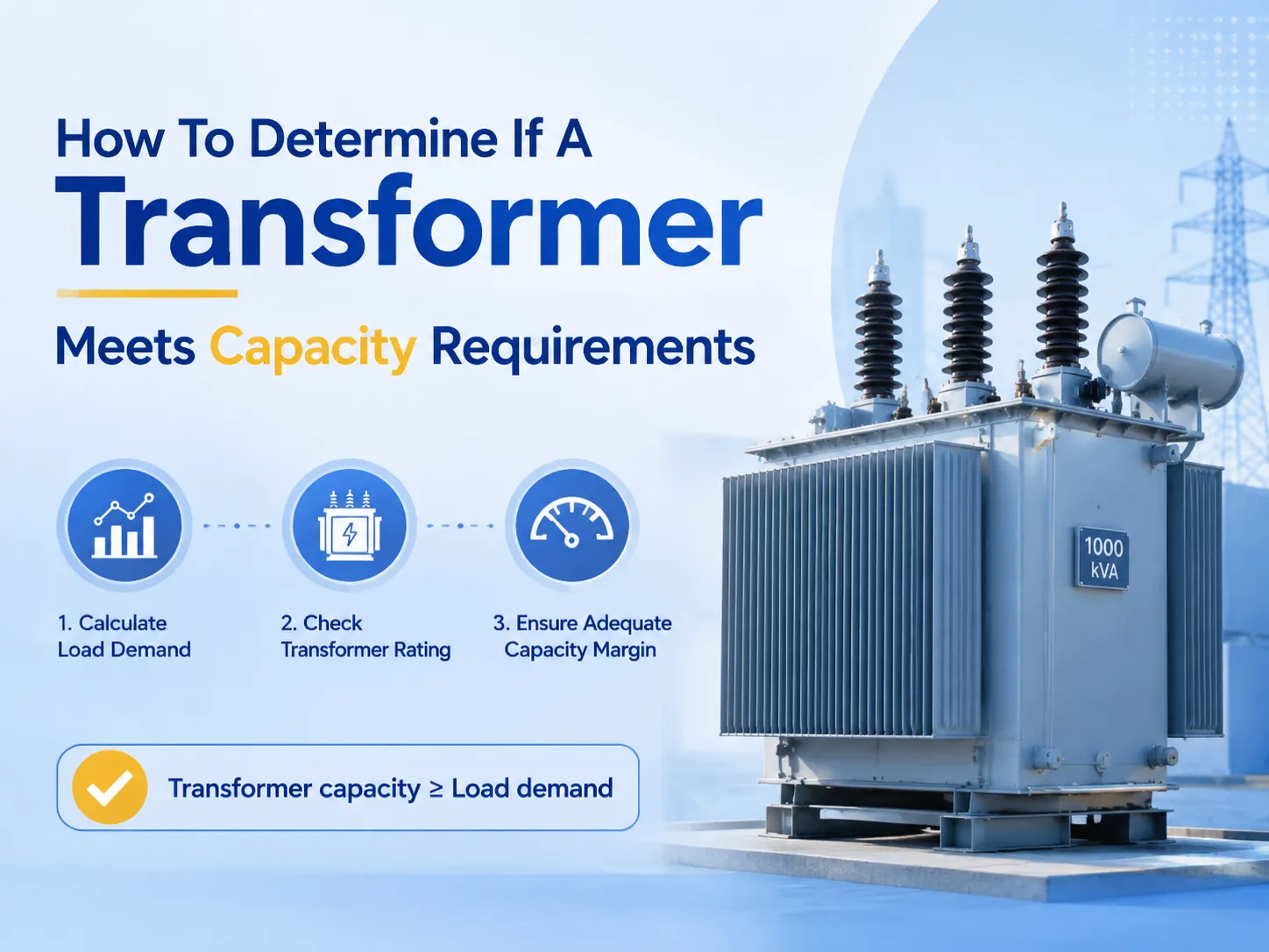
Was bedeutet “Kapazitätsanforderungen” für einen Transformator?
Die Kapazität eines Transformators ist seine angegebene Scheinleistung in kVA oder MVA unter bestimmten Kühlbedingungen. Der Hersteller legt diese Bewertung gemäß IEC 60076-1 oder IEEE C57.12.00 fest, wobei die höchste Scheinleistung des Geräts angegeben wird, die kontinuierlich genutzt werden kann, ohne die Temperaturerhöhungsgrenzen zu überschreiten — normalerweise 65 °C durchschnittliche Wickeltemperaturerhöhung für ölgetauchte Transformatoren und 100–150 °C für trockene Typen, abhängig von der Übereinstimmung der Isolierklasse.
Wenn es um die Einhaltung der “Kapazitätsanforderungen” geht, bedeutet dies, dass der Transformator in der Lage ist, die erhöhte momentane Last zu tragen, vorausgesetzt, es gibt genügend Spielraum für drei Parameter, die Ingenieure berücksichtigen müssen: Einschaltstrom, der durch den Start eines Motors verursacht wird (dies könnte 5–8 des Nennstroms erreichen), harmonische Ströme, die durch Frequenzumrichter entstehen, und die Aussichten auf zukünftige Laststeigerungen. In ein paar Jahren könnte der heute korrekt berechnete Transformator leicht falsch dimensioniert werden, wenn eine zusätzliche Last auf den Betrieb der Anlage gelegt wird.
Es gibt zwei Gründe, warum die oben genannten Missverhältnisse auftreten. Zunächst einmal neigen Käufer dazu, kVA (scheinbare Leistung) mit kW (wirkliche Leistung) zu verwechseln, wodurch sie den Fakt verlieren, dass die Last, die mit einem Leistungsfaktor von 0,8 betrieben wird, 25% mehr kVA im Vergleich zu kW benötigt. Darüber hinaus können Käufer die Nennwerte jedes Geräts summieren, ohne den notwendigen Diversitätsfaktor anzuwenden, was dazu führt, dass sie die Transformatorleistung um etwa 30–50% überschätzen, ohne dass es tatsächlich notwendig ist, für Schaltungen zu bezahlen, die später möglicherweise nicht genutzt werden.
Schritt 1: Berechnen Sie die tatsächliche angeschlossene Last
Zunächst ist es notwendig, Listen aller (Lasten) zu erstellen, die vom Transformator versorgt werden, und diese zu gruppieren. Eine gute Klassifizierung ist die folgende:
- Dauerlasten — Beleuchtung, HVAC und Prozessequipment, das über einen langen Zeitraum arbeitet.
- Intermittierende Lasten — Pumpen, Kompressoren, Kräne, die immer wieder ein- und ausgeschaltet werden.
- Motorlasten — Nennstrom, Anlaufstrom und ob die Ausrüstung Weichstarter, VFDs oder nicht verwendet (wie viele Ströme sie verwendet).
- Nichtlineare Lasten — VFDs, Gleichrichter und USV-Systeme, die harmonische Ströme erzeugen.
Jetzt sollten Sie die kVA aller Lasttypen summieren. Berechnen Sie nicht nur die kW-Werte für jede Last. Wenn Sie nur kW und den Leistungsfaktor haben, finden Sie kVA mit der folgenden Formel. Sobald Sie die Rohdaten als Summe aller Lasten haben, müssen Sie den Diversitätsfaktor anwenden.
| Lastkategorie | Typischer Diversitätsfaktor | Empfohlene Nachfragemarge |
|---|---|---|
| Allgemeine kommerzielle (Einzelhandel, Büro) | 0.60–0.75 | 10–15% |
| Industrieprozessanlagen | 0.70–0.85 | 10–20% |
| Krankenhäuser, kritische Infrastruktur | 0.90–1.00 | 15–25% |
| Rechenzentren (hohe Dichte) | 0.95–1.00 | 20–30% |
| Schulen, kommunale Gebäude | 0.50–0.70 | 10% |
Erhöhen Sie die diversifizierte Nachfrage um 10% bis 20%, da dieser Spielraum sicherstellt, dass die Einheit während der Spitzenlasten im Sommer und auch nach zukünftigen Nachrüstungen innerhalb ihrer thermischen Grenzen bleibt. Dieser Spielraum ist die kosteneffektivste Form der Versicherung, die zum Zeitpunkt der Auswahl verfügbar ist.
Schritt 2: Wenden Sie die kVA-Berechnungsformeln an
Jetzt konvertieren Sie alles in kVA, um es mit der angegebenen Nennleistung zu vergleichen. In diesem Fall sind drei Gleichungen erforderlich, die auf den Gesetzen der Wechselstromleistung basieren.
Im Fall von einphasig: kVA = (Volt × Ampere) ÷ 1000
Im Fall von dreiphasig: kVA = (√3 × Volt × Ampere) ÷ 1000
Im Fall der Umwandlung von kW in kVA: kVA = kW ÷ Leistungsfaktor
Beispiel für die Berechnung: Im Fall einer dreiphasigen Leitung, die mit 480 V und 240 A betrieben wird, beträgt die Nachfrage (1,732 × 480 × 240) ÷ 1000 = 199,5 kVA. Wenn der Leistungsfaktor von 0,85 berücksichtigt wird, bedeutet dies, dass die tatsächlich verbrauchte Energie 170 kW entspricht.
| Nennleitungs-Spannung (V) | Vollaststrom (A) | Berechnete Nachfrage (kVA) | Nächster Standardwert (kVA) |
|---|---|---|---|
| 240 (einphasig) | 100 | 24.0 | 25 |
| 480 (dreiphasig) | 120 | 99.8 | 112.5 |
| 480 (dreiphasig) | 240 | 199.5 | 225 |
| 480 (dreiphasig) | 480 | 399.1 | 500 |
| 800 (dreiphasig) | 25 | 597.5 | 750 |
| 800 (dreiphasig) | 42 | 1003.8 | 1250 |
Gehen Sie immer zum nächsthöheren Standard IEC-Rating (25, 50, 100, 160, 250, 400, 500, 630, 800, 1000, 1250, 1600, 2000, 2500 kVA), anstatt zu versuchen, die minimale verfügbare Leistung zu erhalten. Dies liegt daran, dass Standard-IEC-Bewertungen so gestaltet sind, dass sie zu Standardtransformator-Designs, Kerngrößen und Prüfgeräten passen; spezielle Bewertungen werden mehr kosten — tatsächlich 15 bis 30 Prozent mehr — und länger für die Lieferung benötigen.
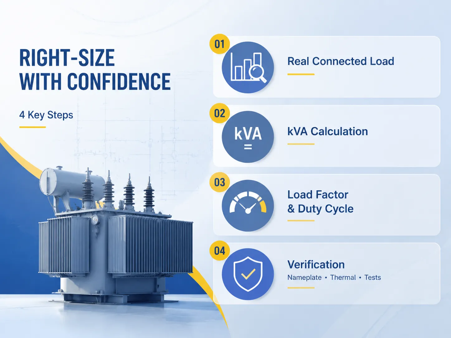
Schritt 3: Überprüfen Sie den Lastfaktor und den Betriebszyklus
Die Gesamtkapazität wird nicht nur durch das maximale Volumen, sondern auch durch die Dauer der Hochspannungsoperationen bestimmt. Daher wird der Lastfaktor als das Verhältnis des durchschnittlichen Verbrauchs zum maximalen Verbrauch zu einem bestimmten Zeitpunkt in der folgenden Formel definiert:
Lastfaktor = Durchschnittlicher Verbrauch ÷ Maximaler Verbrauch
Ein Werk, das 400 kVA nur eine halbe Stunde am Morgen verbraucht und einen durchschnittlichen Verbrauch von 150 kVA hat, hat einen Lastfaktor von etwa 0,375. Diese Situation ist vorteilhaft für die Verwendung eines Transformators mit niedriger thermischer Trägheit, da ein ölgefüllter Transformator vorübergehende Überlastungen von 1,3–1,5 mal der Nennkapazität für mehrere Stunden gemäß IEC 60076-7 bezüglich zyklischer Lasten aushalten kann. Andererseits leidet ein Transformator, der kontinuierlich unter 85%-Last betrieben wird, unter vorzeitigem Altern der Isolierung.
Die Lebensdauer der Isolierung gemäß dem Arrhenius-Gesetz wird mit jedem Anstieg von 6-8°C am kontinuierlich funktionierenden Hochpunkt um die Hälfte reduziert. Wenn beispielsweise ein Transformator mit 90% belastet wird und der Anstieg weniger als 65°C beträgt, liegt die Temperatur des heißen Punktes für längere Zeit über 105 C°. Deshalb ist das 80%-Belastungskriterium nicht nur ein Marketingtrick.
Schritt 4: Verifizierungsmethoden (Typenschild, Thermisch, Tests)
Nachdem der Transformator eingerichtet wurde, müssen Sie die Kapazität auf drei verschiedenen Ebenen bewerten. Zuerst müssen Sie den administrativen Aspekt überprüfen: Sie müssen die Plattenbewertung, den Impedanzwert, die Vektorgroup und die Kühlklasse ONAN, ONAN/ONAF, AN/AF anhand der Einkaufsspezifikationen und der Laststudie überprüfen. Der zweite Aspekt, den Sie überprüfen müssen, ist der betriebliche Aspekt, bei dem Sie den sekundären Strom, die Spannung und die Temperatur der Wicklung überprüfen müssen.
Es ist wichtig, den Hersteller nach dem Fabrikbericht für neue Transformatoren zu fragen. Laut IEC 60076-1 sollten Routineprüfungen hinsichtlich des Wicklungswiderstands, des Verhältnisses, der Leerlaufverluste, der aktiven Verluste und der Temperaturanstiegstests durchgeführt werden. Dies ist der einzige labortechnische Nachweis, auf den Sie sich verlassen können, um zu beweisen, dass der Transformator kontinuierlich bei der Nennleistung in kVA betrieben werden kann, ohne die Grenze der Isolierungstemperatur zu überschreiten.
| Verifizierungsmethode | Was es bestätigt | Typische Kosten / Aufwand |
|---|---|---|
| Typenschildüberprüfung vs. Laststudie | Bewertung, Impedanz, Kühlklasse stimmen überein | Keine Kosten, 1 Stunde |
| Eine Woche Nachfrageprotokollierung | Spitzen-kVA vs. Bewertung unter realer Belastung | $200–$600 (Logger-Miete) |
| Infrarot-Thermografie | Hotspots an der Durchführungen, dem Tank und den Kabelverbindungen | $300–$800 pro Untersuchung |
| Gelöste Gasanalyse (DGA) | Frühe thermische/ Lichtbogenfehler in Öleinheiten | $80–$200 pro Probe |
| Fabrik-Routine-Testbericht | Verhältnis, Verluste, Isolierung, Temperaturanstiegsnachweis | Inklusive im Kauf |
Für Einheiten, die überlastet zu sein scheinen, führen Sie zuerst eine DGA und eine Temperaturuntersuchung durch, bevor Sie in Betracht ziehen, etwas anderes zu kaufen. Oft ist das eigentliche Problem eine schlechte Verbindung oder eine Blockade der Kühlrippen und nicht der Kern selbst; der Austausch oder die Verbesserung dieser kann die volle Funktion zu geringeren Kosten als der Kauf eines neuen Transformators wiederherstellen.
Häufige Kapazitätsbewertungen und deren Lastgrenzen
Die bereitgestellte Tabelle zeigt die empfohlenen Standardbewertungen und die maximalen nachhaltigen Lasten für alle in Betracht gezogenen Kühltechnologien, die auf diversifizierten Bedürfnissen und normalen klimatischen Bedingungen von 30 Grad Celsius (Durchschnittstemperatur) basieren.
| Nenn-kVA | Typische Spannungsklasse | Max. nachhaltige Last — Trockenbau (AN) | Max. nachhaltige Last — Ölgetaucht (ONAN) | Typische Preisspanne (FOB China) |
|---|---|---|---|---|
| 100 | 0,4/0,4 kV, 11/0,4 kV | 80–90 kVA | 70–80 kVA | $2.500–$6.000 |
| 250 | 11/0,4 kV | 200–225 kVA | 175–200 kVA | $4.500–$11.000 |
| 500 | 11/0,4 kV, 33/0,4 kV | 400–450 kVA | 350–400 kVA | $8.000–$18.000 |
| 1000 | 10/0,4 kV, 35/10 kV | 800–900 kVA | 700–800 kVA | $15.000–$32.000 |
| 1600 | 35/10 kV, 33/0,4 kV | 280–1.440 kVA | 120–1.280 kVA | $24.000–$48.000 |
| 2500 | 35/10 kV | 000–2.250 kVA | 750–2.000 kVA | $38.000–$75.000 |
Es muss darauf hingewiesen werden, dass die angenommenen kontinuierlichen Versorgungsgrenzen unter den Bedingungen einer sauberen Versorgung und eines Leistungsfaktors an den Anschlüssen des Transformators, der fast eins entspricht, gelten. Wenn man jedoch Harmonische berücksichtigt, wird die Situation ganz anders. Zum Beispiel verursacht eine 20-% Gesamtverzerrung des Stroms einen Anstieg der effektiven thermischen Belastung um 5 bis 10%, und ein bereits laufendes Gerät kann sich unter einer Überlastung befinden, obwohl seine kVA innerhalb der normalen Grenzen zu liegen scheint.
Spezifikationen, die die Kapazität beeinflussen
Neben der kVA-Bewertung beeinflussen mehrere andere Nameplate-Spezifikationen die tatsächliche Kapazität, die der Transformator in Ihrer Anwendung bereitstellt:
- Kühlklassifikation (IEC 60076-2): Ein ONAN-Transformator kühlt sich selbst auf seine volle Nennleistung. Ein ONAN/ONAF-Transformator hat zusätzliche aktive Lüfter, die etwa 20-30 % mehr als seine Standardbewertung bereitstellen.
- Temperaturerhöhung (K): Ein Transformator mit einer Nennleistung von 65 K hat eine höhere Kapazität als ein Transformator mit einer Nennleistung von 55 K derselben Größe, unterliegt jedoch einer stärkeren Abnutzung seiner Isolierung.
- Impedanzspannung (uk%): Sie liegt normalerweise zwischen vier und zehn Prozent für Verteilungstransformatoren. Ein höherer Impedanzwert reduziert den Fehlerstrom, hat jedoch schlechtere Spannungsabfallmerkmale.
- Vektorgruppe (Dyn11, Yyn0, Yd11): Muss zum System passen, um Probleme mit zirkulierenden Strömen zu vermeiden.
- Herabstufung aufgrund von Höhe und Temperatur: Wenn die Höhe über 1000 m steigt und die Temperatur 40 °C überschreitet, sollten die Transformatoren gemäß IEC 60076-1 herabgestuft werden (allgemein 0,5 % bis 1 % jeweils 100 m über 1000 m).
- Material für Wicklungen: Kupferwicklungen haben eine etwa 15% bis 25% höhere Kurzschlusskapazität als Aluminiumwicklungen, sind jedoch auch etwa 20% bis 40% teurer.
Marken und Preisspannen für kapazitätsgradierte Einheiten
Bei ausländischen Produkten ist die Kapazitätsvalidierung von größter Bedeutung, da der Unterschied zwischen den Leistungsspezifikationen und der tatsächlichen Leistung zunimmt, wenn Kunden das Produkt nicht physisch im Werk überprüfen können. Internationale Marken verlangen mehr für ihre Nennkapazität, während chinesische Hersteller fast die gleiche validierte Kapazität zu viel niedrigeren Preisen anbieten.
| Marke | Typischer Bereich | Bemerkenswerte Position | Richtpreis (500 kVA) |
|---|---|---|---|
| ABB | Verteilung bis 50+ MVA | Globaler Marktführer, starkes Servicenetzwerk | $18.000–$30.000 |
| Siemens | Verteilung zur Übertragung | Hoch effiziente amorphe Kernoptionen | $18.000–$32.000 |
| Schneider Electric | Trockenbauverteilung | Tiefe Niederspannungsintegration | $15.000–$28.000 |
| Hitachi Energie | Versorgungs- und Industrieanwendungen | Expertise in Netzstärke und HVDC | $17.000–$30.000 |
| Eaton | Verteilung, Pad-Montage | Starke Präsenz in Nordamerika | $14.000–$26.000 |
| CG Power, TBEA | Versorgungs- und Industrieanwendungen | Großvolumenhersteller | $10.000–$18.000 |
| Jiangsu Subian Electric Power | 10 kVA–100 MVA | IEC 60076-zertifiziert, vollständige Werkprüfberichte, Kupferwicklungen Standard | $8.000–$16.000 |
Die oben genannten Preise sind nur Schätzungen, basierend auf FOB China / ab Werk, für die 500 kVA-Klasse. Preisvariationen hängen von den Kundenanforderungen und Anwendungsfällen ab. Die oben genannten internationalen Marken sind nur eine Auswahl vieler Wettbewerber auf dem Markt mit jahrelanger Erfahrung. Was macht Jiangsu Subian Electric Power für jemanden mit Kapazitätsanforderungen besonders? Alle Einheiten kommen mit dem IEC 60076-Bericht für Routineprüfungen sowie Kupferwicklungen als Standard. Im Wesentlichen weiß ein Käufer genau, was er/sie mit der Einheit erhält. Diese Informationen erleichtern den Entscheidungsprozess, da die Kapazitätsanforderungen im Bericht dargestellt sind. Bei Zweifeln bezüglich der Parameter kann der Kunde immer die Werkberichtszahlen mit den Berechnungen in dieser Studie abgleichen.
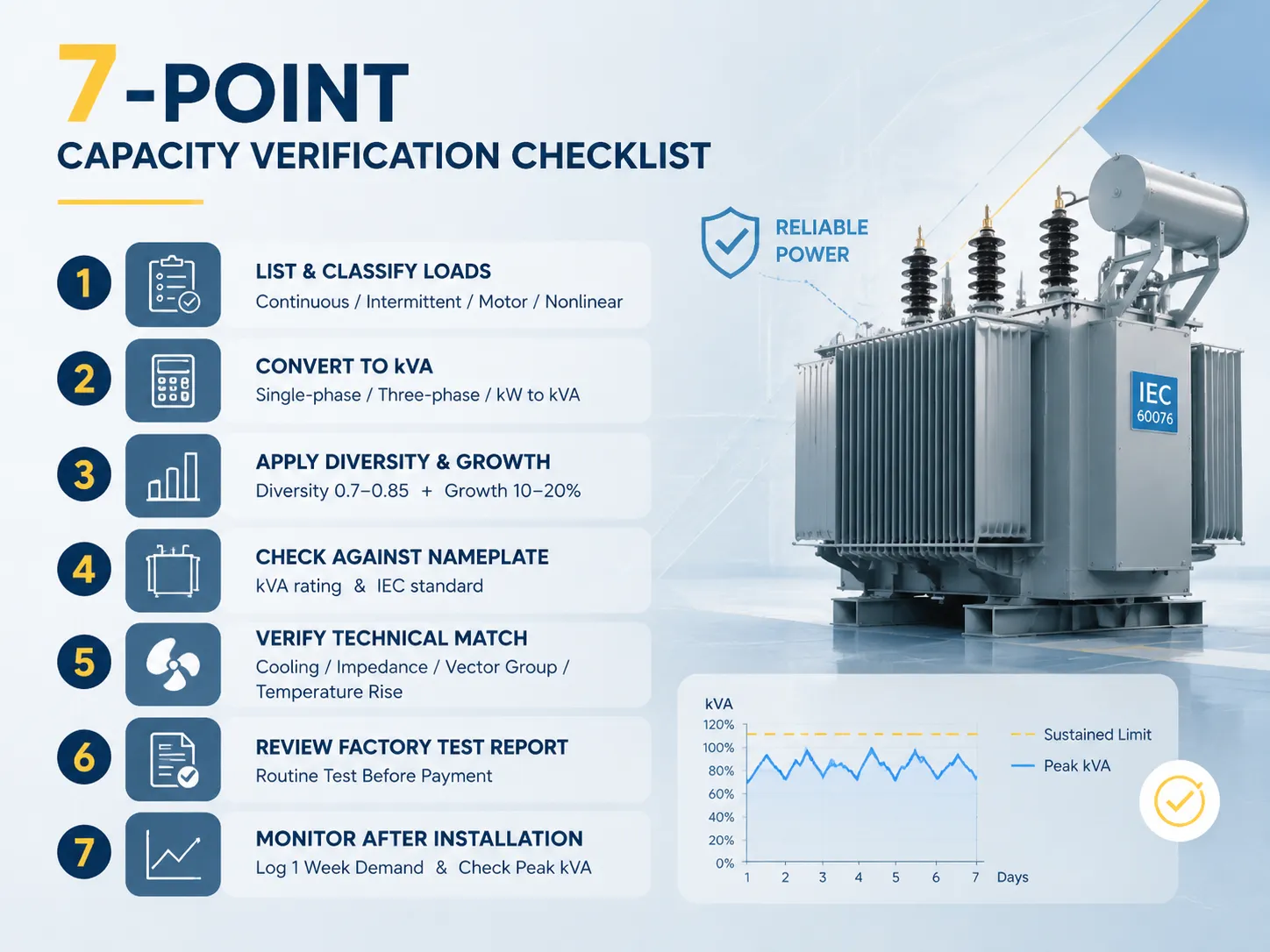
Eine 7-Punkte-Kapazitätsverifizierungs-Checkliste
- Sie sollten eine umfassende Liste aller Lasten erstellen und diese als kontinuierlich, intermittierend, Motor oder nichtlinear gruppieren.
- Sie müssen jede Last in kVA umrechnen, basierend auf der Einphasen-, Dreiphasen- oder kW-zu-kVA-Umrechnungsformel.
- Sie sollten einen Diversitätsfaktor (der normalerweise irgendwo im Bereich von 0,7 bis 0,85 für Industrieanlagen liegt) und einen Wachstumsfaktor von etwa 10 bis 20 Prozent nutzen.
- Sobald Sie diese Zahlen erhalten haben, können Sie sie mit der Nennleistung in kVA abgleichen und sicherstellen, dass sie im Bereich der Standard-IEC-Werte liegen.
- Stellen Sie sicher, dass die Kühlklasse, die Impedanz, die Vektorgruppe sowie der Temperaturanstieg den Systemstandards entsprechen.
- Um sicherzustellen, dass alles in Ordnung ist, sollten Sie die Berichte über die routinemäßigen Fabriktests anfordern und lesen, bevor Sie eine Zahlung leisten.
- Nachdem Sie das System installiert haben, überwachen Sie dessen Nachfrage eine Woche lang und stellen Sie fest, dass die Spitzen-kVA den vorgeschriebenen Wert nicht überschreiten.
Häufig gestellte Fragen
Wie erkenne ich, ob mein Transformator überlastet ist?
Vergleichen Sie die durchschnittliche Nachfrage der letzten 15 Minuten mit der Nennkapazität des Transformators. Wenn der Durchschnitt konstant 80% der Kapazität für öltypische Transformatoren oder 90% für trockene Typen überschreitet, bedeutet dies, dass das Gerät tatsächlich überlastet ist. Zu den Anzeichen einer Überlastung, die beobachtet werden können, gehören die Öltemperatur über 90 °C (man kann Papier der Klasse A verwenden), Hot-Spot-Messungen, die über 105 °C liegen, Geräusche im Tank und die Gaszusammensetzungsanalyse von Gasen wie Wasserstoff und Ethylen. Man könnte das Problem durch Lastumverteilung, Kühlung oder den Austausch des Transformators gegen den nächsthöheren Standardwert bewältigen.
Was ist der Unterschied zwischen kW und kVA in der Transformatorenkapazität?
kW steht für die tatsächliche Leistung, während kVA für die Scheinleistung steht. kW kann mit der Formel kVA = kW ÷ Leistungsfaktor berechnet werden. Zum Beispiel, wenn der Leistungsfaktor 0,8 beträgt, benötigt eine Leistung von 100 kW Transformatoren mit einer Kapazität von 125 kVA. Das Typenschild des Transformators ist immer in kVA, da die gesamte thermische Kapazität des Transformators von der Wicklung abhängt. Wenn der Leistungsfaktor weniger als eins beträgt, erfüllt der Transformator möglicherweise nicht die Anforderungen, wenn er nur mit kW berechnet wird.
Welchen Lastfaktor sollte ich bei der Dimensionierung eines Transformators verwenden?
Verwenden Sie den tatsächlichen Diversitätsfaktor der Lasten in der Einrichtung: 0,6–0,75 (für Bürogebäude), 0,7–0,85 (für Industrieanlagen), 0,9–1,0 (für Krankenhäuser oder Rechenzentren). Verwechseln Sie diese Faktoren nicht — den Diversitätsfaktor und den Lastfaktor (Durchschnitt ÷ Spitzenbedarf). Wenn Sie es mit einer neuen Einrichtung zu tun haben, verwenden Sie einen Bedrohungsfaktor von 0,75 mit einer Wachstumsreserve von 15–20%. Falls Sie mit einer bestehenden Einrichtung arbeiten und alle Versorgungsrechnungen der letzten 12 Monate haben, müssen Sie nur Ihren Lastfaktor berechnen.
Kann ein Transformator vorübergehend über seiner Nenn-kVA betrieben werden?
Ja, das kann er, es ist jedoch nur unter strengen Bedingungen erlaubt. Laut IEC 60076-7 kann der ölgetauchte Transformator mit ONAN-Kühlsystem bis zu 1,3 seiner Nennlast bewältigen, vorausgesetzt, dass er 70% nicht überschreitet und die Betriebstemperatur unter 120 °C bleibt. Jede Stunde Überlastbetrieb würde die Lebensdauer der Isolierung erheblich verkürzen — beispielsweise würde die Isolierung bei einer Temperatur von 110 °C nur einige Jahre anstelle von mehreren Jahrzehnten bei ordnungsgemäßer Nutzung funktionieren.
Was kostet ein zusätzlicher 10% Kapazitätszuschlag?
Wenn der Transformator eine Kapazität von 500 kVA hat, würde der Erwerb des neuen Transformators mit einer Kapazität von 630 kVA Sie 15–25% mehr kosten (was etwa $2.000–4.000 bedeutet). Wenn Sie in Betracht ziehen, den Transformator nach einem Ausfall zu ersetzen, sollten Sie bereit sein, für das neue Gerät $8.000–18.000 zu zahlen und bis zu 1–4 Wochen auf dessen Lieferung zu warten. Wenn Sie es vermeiden können, die Last nur einmal während 20 Jahren abzuschalten, hätte sich Ihre Investition in einen Spielraum von 10–20% bereits ausgezahlt.
Referenzen
- IEC 60076-1: Leistungstransformatoren — Allgemeines — der internationale Standard, der die Bewertungen, Kapazitäten und Prüfanforderungen von Transformatoren definiert.
- IEC 60076-7: Leistungstransformatoren — Lastleitfaden für ölgetauchte Transformatoren — der autoritative Leitfaden für zyklische Überlast- und Temperaturgrenzen.
- IEEE C57.12.00: Allgemeine Anforderungen für flüssigkeitsgetauchte Verteilungs-, Leistungs- und Regeltransformatoren — nordamerikanisches Äquivalent für Kapazitäts- und Prüfstandards.
- Electrical4U — Transformatorlastfaktor und Effizienz — eine klare Erklärung von Lastfaktor, Diversität und Effizienzkurven.
- Eaton — Transformatorgrößentabelle — praktische kVA-Berechnungstabellen und Größenbeispiele, die in der Branche verwendet werden.
- Fluke — Thermografie von Transformatoren — praktische Anleitung zur Infrarotüberprüfung von Last und Verbindungen.
- Wikipedia — Transformator — Hintergrund zur Transformatorentheorie, Bewertungen und Kühlklassifikationen.
Fazit
Zu wissen, ob die Kapazität Ihres Transformators ausreichend ist, ist keine Frage spekulativer Schätzungen über die Nachfrage. Der Prozess umfasst vier einfache Schritte: Bestimmung der Spitzenlast, Berechnung der Nachfrage in kVA, Bestimmung des Lastfaktors und Überprüfung der Namensplattendaten, die durch werkseitig bereitgestellte Testergebnisse unterstützt werden. Die Regel, eine Erhöhung von 10–20% zuzulassen und den Lastfaktor für ölgefüllte Transformatoren unter 80% zu halten, ist heute recht kostengünstig und kann kostspielige Ausfälle in der Zukunft verhindern.
- Führen Sie die Berechnungen in kVA durch und verwenden Sie einen Diversitätsfaktor zwischen 0,7 und 0,85 für gemischte industrielle Lasten.
- Überprüfen Sie die Kapazität mit dem IEC 60076-Bericht — das ist der einzige Nachweis, nicht der Katalog.
- Berücksichtigen Sie einen Spielraum von 10-20% für zukünftige Bedürfnisse — das ist die günstigste Form der Versicherung in der Beschaffungsphase.
- Wählen Sie den Anbieter basierend auf der getesteten Kapazität und dem Grad der Transparenz, nicht nach dem Preis pro kVA.