


At a steel mill, an arc furnace transformer is positioned only a few meters from white-hot steel with a secondary current of 40,000 A. In a semiconductor factory, the main transformer steps down 110 kV down to 20 kV for a facility that cannot tolerate a second of unplanned downtime. Main transformers, indeed, are the backbone of the industrial world, transferring high-voltage supply from the utility line and then delivering it in so-called low voltage to plants’ switchgear, engines, and furnaces.
In this article, you will find out what the main transformer is, how to tell it from distribution and unit transformers, how to size and specify one for the industrial facility, and what price it costs in terms of efficiency, impedance, cooling, protection, and price. No matter whether you are an electrical engineer, plant engineer, or purchasing manager, this guide provides you with all the needed technical and commercial data to make the right choice.
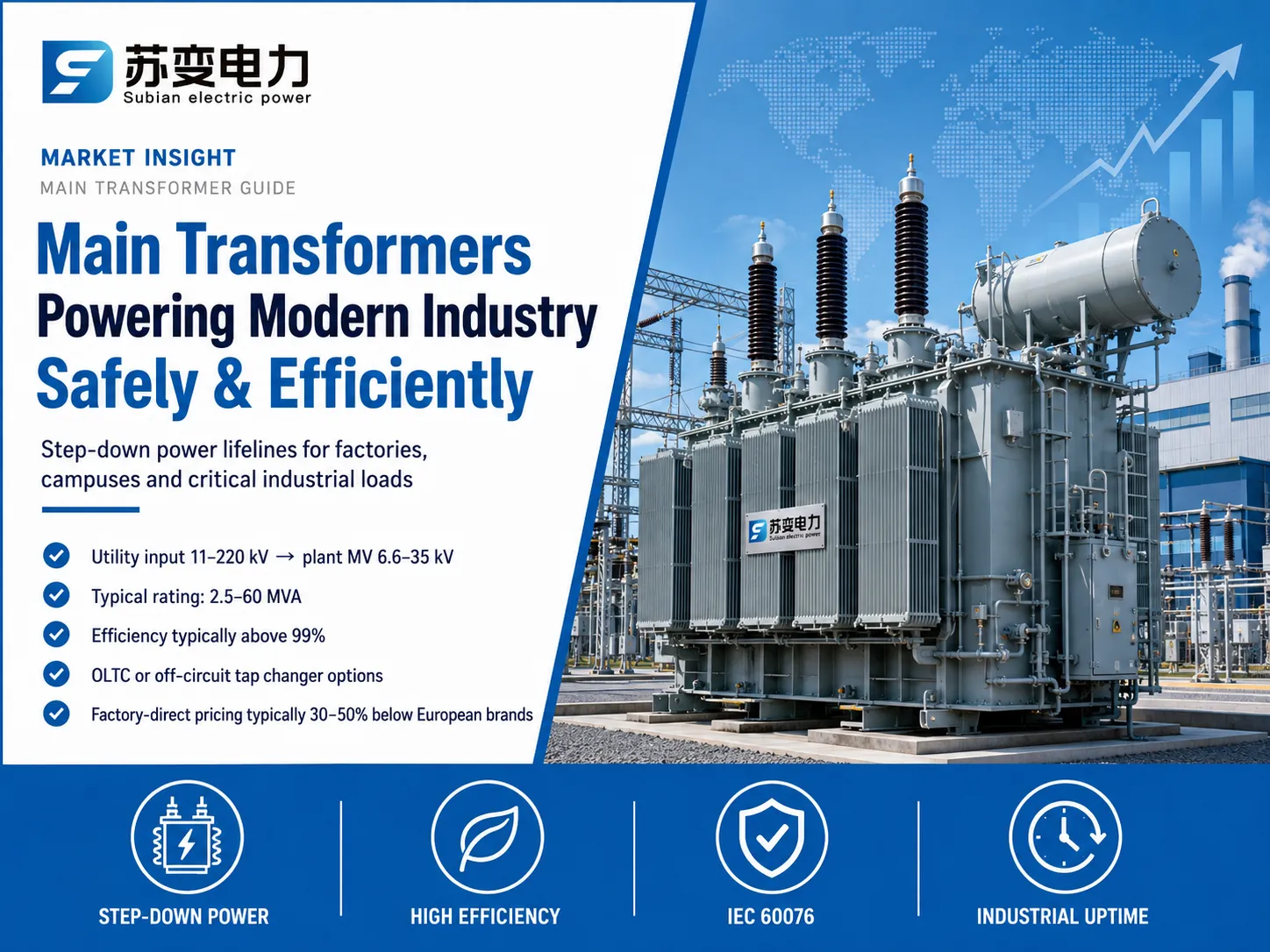
What Is a Main Transformer? (Definition)
The main transformer in an industrial, commercial or utility facility is the biggest power transformer — the appliance connecting the facility to the grid and supplying all the internal distribution network. In a steel mill, for example, it might be a 40MVA/110kV unit, while a medium-size factory makes use of a 2.5MVA/11kV unit, and a hospital campus will, probably, apply several 2MVA units in order to provide redundancy. The reason the device is called a main transformer lies not in the voltage values, but in the position of the transformer as the key electric component of the plant.
The main transformers are manufactured to operate with a maximum reliability because they include the best solution regarding the losses, high-quality insulation, functioning tap changers, and proper protection solutions. The price of the main transformer malfunction implies not only the repair expenses; in case of the process plant the losses from the breakdown may be measured in millions of dollars.
The Role of the Main Transformer in an Industrial Power System
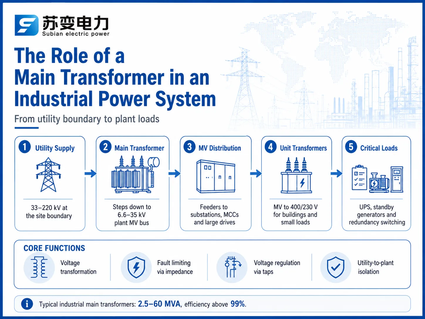
The power structure of modern industrial installations follows a largely similar pattern:
Utility connection — which ranges from 33 kV to 220 kV, is located at the boundary of the installation (the point where external power supply is connected to the electrical system of the facility).
Main transformer — which generates the supply voltage from 6.6 kV to 35 kV for the facility itself.
Medium-voltage distribution system — which includes power connections to substations, motor control centers, and major drives.
Unit transformer — which steps the supply voltage down from 6.6 kV up to 35 kV to produce 400 and 230 V and supply electricity to buildings and small loads.
Critical loads — which is represented by uninterruptible power supply (UPS), backup generators, and redundant switches installed.
In that framework, the main transformer not only converts voltage but also protects the whole circuit from faults due to its impedance, controls voltage due to the availability of taps, and separates the utility network from the facility.
How to Size a Main Transformer for a Facility
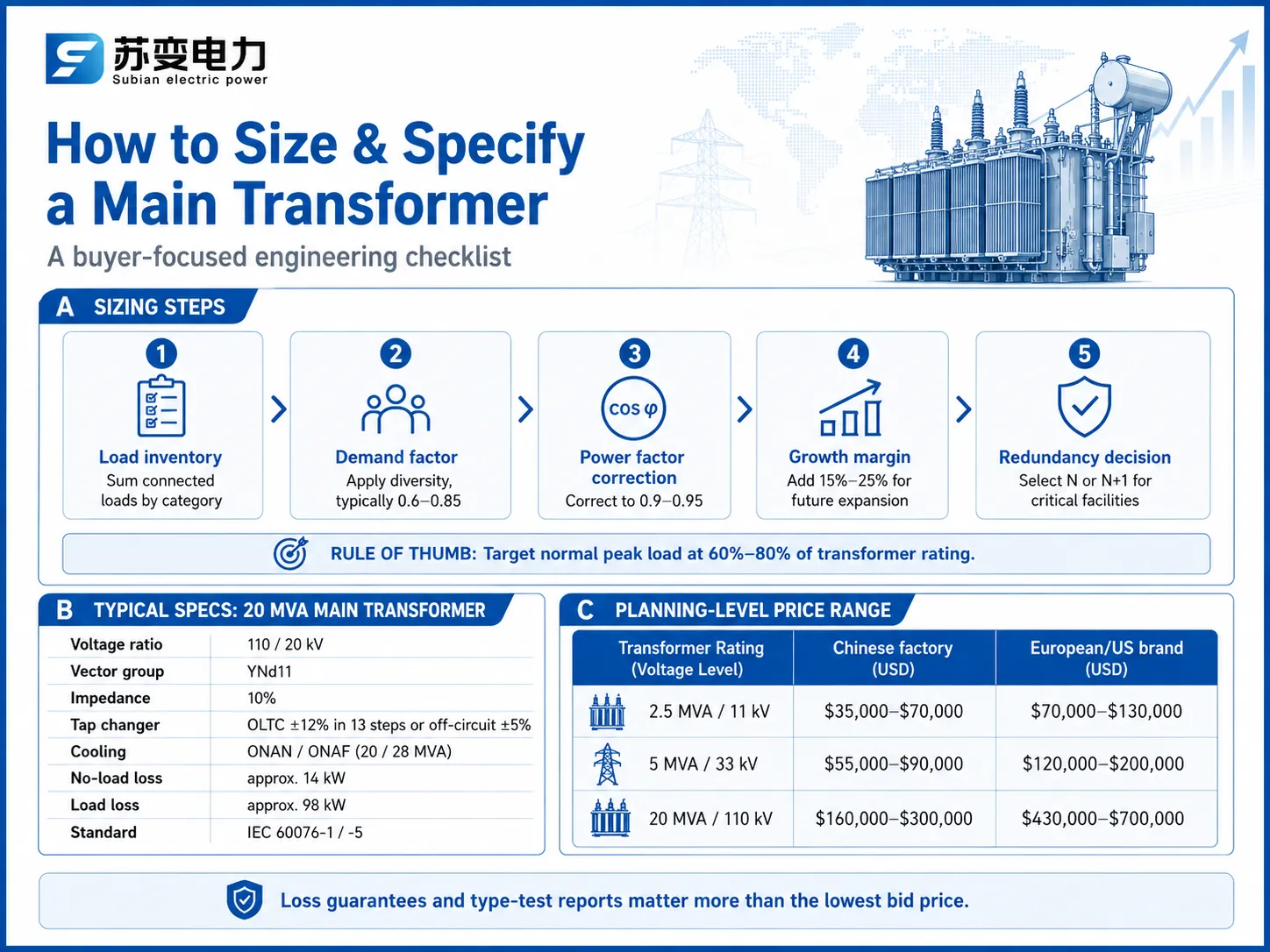
Sizing is the decision that drives every other specification. The engineering sequence:
| Step | Method | Typical Result |
|---|---|---|
| 1. Load inventory | Sum connected loads by category | e.g. 8 MW connected |
| 2. Demand factor | Apply diversity (0.6–0.85 typical) | e.g. 6 MW maximum demand |
| 3. Power factor correction | Compensate to 0.9–0.95 | ≈6.5–7 MVA apparent |
| 4. Growth margin | Add 15%–25% for future | ≈8–8.5 MVA selected |
| 5. Redundancy decision | N or N+1 configuration | 2×8 MVA if critical |
A solid guideline for industrial facilities is to size the principal transformer so that the regular peak load falls between 60 percent and 80 percent of its rating. This ensures that there is room for overloads, that efficiency is maximized, and that there is sufficient margin for the drop in power when motors start. For critical plants, the use of two transformers in N+1 configuration (where both transformers can manage the entire load in case of an emergency) has become quite normal.
Main Transformer Types & Configurations
| Configuration | Voltage Step | Typical Rating | Where Used |
|---|---|---|---|
| Two-winding, oil-immersed | 110/20 kV | 5–60 MVA | Most industrial sites |
| Two-winding, dry-type | 11/0.4 kV or 20/0.4 kV | 0.5–10 MVA | Indoor, fire-sensitive facilities |
| Three-winding | 110/20/6.6 kV | 10–60 MVA | Plants with multiple voltage levels |
| N+1 twin bank | 110/20 kV ×2 | 2×5–2×30 MVA | Data centers, hospitals, refineries |
Three-winding main transformers are popular where a site needs both a medium-voltage process bus and a separate auxiliary bus; the third winding also provides a harmonic path and reduces the need for a separate unit transformer.
Main vs. Distribution vs. Unit Transformer
| Aspect | Main Transformer | Distribution Transformer | Unit Transformer |
|---|---|---|---|
| Position | Utility boundary to plant MV | MV feeder to end user | Plant MV to LV loads |
| Typical rating | 2.5–60 MVA | 50 kVA–2,500 kVA | 100 kVA–3 MVA |
| Primary voltage | 11–220 kV | 2.4–35 kV | 6.6–35 kV |
| Duty profile | Continuous high load + overload | Variable partial load | Building/process loads |
| Typical price | $35k–$300k+ | $1.5k–$45k | $5k–$70k |
The line between “main” and “unit” can blur in small facilities where a single transformer does both jobs, but the engineering priorities differ: main transformers optimize for reliability and continuous load, unit transformers for cost and flexibility.
Key Specifications for Industrial Main Transformers
| Parameter | Typical Value |
|---|---|
| Rated power | 20 MVA |
| Voltage ratio | 110 / 20 kV |
| Vector group | YNd11 |
| Impedance voltage | 10% |
| Tap changer | OLTC ±12% in 13 steps, or off-circuit ±5% |
| Cooling | ONAN/ONAF (20/28 MVA) |
| No-load loss | ≈14 kW |
| Load loss | ≈98 kW |
| Insulation level | 550 kV BIL (110 kV side) |
| Standard | IEC 60076-1/-5 |
These numbers are the contract between buyer and manufacturer. Any deviation — higher losses, different impedance, weaker tap range — changes the price and the performance, so they must be locked before production.
Efficiency, Losses & Total Cost of Ownership
Most industrial main transformers operate with efficiency levels between 99.0% and 99.6%. For example, at an efficiency of 99.4% for a 20 MVA transformer, the heat loss amounts to around 120 kW for full load operation, which comes out to about 1,000 MWh of total consumption in one year of operation. That means costs amounting to $80,000–150,000 per year at average tariffs of $0.08–0.15/kWh, not counting the losses that occur during standby time.
The effective cost assessment should be carried out over a period of 20–30 years in other words. The creation of low-loss models takes about 5%–10% more to produce, but they save money on operational costs in the long run. Cutting off 5 kW of losses for the 20 MVA transformer unit means savings of approximately 44 MWh annually, which gives savings of somewhere around $4,400–6,600 per year, $90,000–130,000 in 20 years at normal industrial pricing solutions.
Protection & Safety Engineering
The most significant approach of multi layer protection is towards a transformer which has the highest valuation in the location.
Starting with the different protection schema:
Differential protection (87T) which compares currents in primary side of transformer with currents on the secondary side (corrected for ratio and vector groups) to detect internal faults quickly.
Overcurrent protection (50/51) assists in phase and earth fault backup.
Restricted earth fault (REF, 64) assists in detecting winding to ground fault.
Buchholz relay detects failures at early stages due to gas formation; it can also produce surge and wave impulse alarms.
Temperature alarms indicate that the transformer has reached its temperature limit in accordance with the standards set by IEC 60076-2.
Pressure relief, OLTC protection and surge arresters protect transformer from mechanical forces and lightning.
The experience of commissioning and maintenance is adopted from the standards set by IEEE C57.140 (maintenance guide) and IEC 60076-7 (loading guide).
Applications Across Modern Industry
Steel and metallurgy — main + furnace transformers which deal with loads in the range of 30-120 MVA along very arduous duty cycles.
Computer centers — twin main transformers with guaranteed redundancy, often in the range of 2×10-2×30 MVA at the voltage level of 110/20 kV.
Pharmaceuticals & semiconductors — connecting to adverse loads and demanding high-quality voltage in addition to dry-type option choice for installations indoors.
Mining — remote areas with need for specific designs responding to difficult environmental factors, high ambient temperature, bad accessibility conditions.
Chemicals and refining — continuous load technologies usually work on N + 1 basis and support significant excess load capacity.
Commercial buildings and hospitals — 5-20 MVA that are subject to stringent redundancy requirements.
In each situation, the logic behind the purchase will be similar: matching sizes with the characteristics of the loads, optimizing losses with the investments, adding redundancy where downtime means losses, and adding protection with the connections of relays.
Realistic Prices & Top Brands
Main transformer pricing follows rating, voltage, losses, tap changer, and brand. Planning-level ranges for oil-immersed units:
| Rating / Voltage | Chinese Factory (e.g. Subian, TBEA) | European/US Brand |
|---|---|---|
| 2.5 MVA / 11 kV | $35,000–$70,000 | $70,000–$130,000 |
| 5 MVA / 33 kV | $55,000–$90,000 | $120,000–$200,000 |
| 20 MVA / 110 kV | $160,000–$300,000 | $430,000–$700,000 |
| 40 MVA / 110 kV | $300,000–$550,000 | $800,000–$1,300,000 |
Prices vary by specification, loss level, and region. For industrial buyers who need a main transformer engineered to their load profile without the international brand premium, Jiangsu Subian Electric Power is a strong option: a Chinese transformer manufacturer producing distribution and power transformers from 50 kVA to 220 kV class, including 2.5–60 MVA industrial main transformers with custom impedance, tap ranges, and cooling configurations. Units ship with IEC 60076 type-test reports and full factory test documentation, and their engineers support protection interface design and site commissioning. Factory-direct pricing is typically 30%–50% below European equivalents, and OEM/ODM customization is available for complex projects.
Frequently Asked Questions
What is the difference between a main transformer and a unit transformer?
A main transformer connects the facility to the utility grid at 11–220 kV and feeds the whole plant’s MV distribution at 6.6–35 kV. A unit transformer is smaller (usually 100 kVA–3 MVA) and steps the plant’s MV bus down to 400/230 V for buildings, lighting, and small loads. A large site has one or two main transformers and dozens of unit transformers.
How do I size the main transformer for my factory?
Sum the connected loads, apply a demand factor of 0.6–0.85, correct power factor to 0.9–0.95, add 15%–25% growth margin, then select the nearest standard rating so normal peak load sits at 60%–80% of rating. For critical facilities, use N+1 twin units each capable of full load. A 6 MW maximum demand typically leads to an 8–10 MVA transformer.
What efficiency should an industrial main transformer achieve?
Expect 99.0%–99.6% at full load, with no-load loss around 0.05%–0.1% of rating and load loss 0.4%–0.7%. A 20 MVA unit might show 14 kW no-load and 98 kW load losses. Request guaranteed loss values and run a capitalized-loss comparison over 20–30 years before choosing between bids — loss differences usually outweigh price differences.
How much does a main transformer cost for a factory?
Budget $35,000–$90,000 for a 2.5–5 MVA / 11–33 kV unit, $160,000–$300,000 for 20 MVA / 110 kV from Chinese factories (or $430,000–$700,000 from European brands), and up to $1.3 million for 40 MVA class from premium brands. Add 20%–40% for protection, installation, testing, and civil works.
Should my main transformer have an on-load tap changer?
If the utility voltage varies more than ±5% or your loads cause meaningful voltage swings, yes — an OLTC holds plant MV within ±2% automatically over a ±12% to ±16% range. If supply is stable and load is constant, an off-circuit tap changer at ±5% is cheaper and adequate. The OLTC typically adds $15,000–$60,000 depending on rating.
References
- IEC 60076-1: Power Transformers — General — Ratings, tolerances, and tests for main transformers.
- IEC 60076-5: Ability to Withstand Short Circuit — Short-circuit withstand requirements essential for industrial duty.
- IEC 60076-7: Loading Guide for Oil-Immersed Power Transformers — Overload capability and thermal aging guidance.
- IEEE C57.12.00: General Requirements for Liquid-Immersed Transformers — North American companion standard.
- IEEE C57.140: Guide for Transformer Maintenance — The maintenance and condition-assessment reference for industrial units.
- Hitachi Energy Transformers — Industry reference for large transformer technology.
Conclusion
- The main transformers are the critical components in the electrical system of modern industries, as they form the basis of the energy structure of the enterprise. The parameters of size, optimization of losses, type of protection, and redundancy determine the performance and cost of the site for the years to come.
The size should be selected so that normal maximum load is 60%–80% of the rated capacity with a growth margin of 15%–25%.
The losses should be optimized using a 20–30 year capitalized-loss model.
The protection should be provided by means of differential protection, REF, Buchholz relay, and temperature control while maintenance should follow the DGA.
The budget for these transformers should range from $35k to $90k for 2.5–5 MVA and from $160k to $300k for 20 MVA/110 kV (factory-direct).
If you are planning a new plant or upgrading an existing substation, Jiangsu Subian Electric Power can engineer and supply main transformers from 2.5 MVA to 60 MVA with IEC 60076 certification, custom tap and cooling configurations, and factory-direct pricing to match your budget.