


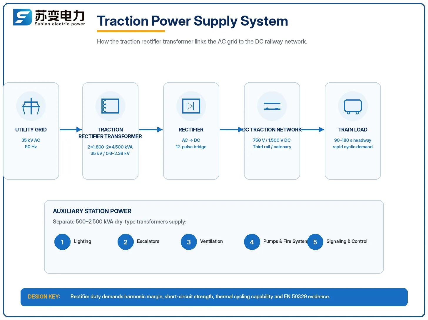
En tant qu'ingénieur en alimentation de traction responsable d'une ligne de métro de 45 km capable de transporter 80 000 passagers par jour avec des intervalles de 90 secondes, vous utiliserez un système d'alimentation de traction fonctionnant en 35 kV AC. Cette distribution AC fournira du courant à douze sous-stations d'alimentation de traction qui convertiront l'énergie en 750 V DC qui sera fournie via un troisième rail. En même temps que ce processus est réalisé, un autre ensemble complet de transformateurs fournira de l'énergie auxiliaire pour l'éclairage à l'intérieur des stations, les escalators, les ventilateurs de ventilation et la signalisation [1].
Le niveau de compétences en ingénierie électrique nécessaire pour travailler avec des transformateurs dans le transport ferroviaire est à un tout autre niveau que toute autre application. L'article décrira les différentes exigences de conception pour les transformateurs dans le transport ferroviaire, y compris les transformateurs redresseurs de traction, les transformateurs auxiliaires, les mesures pour garantir leur conformité aux normes IEC, et les moyens de traiter les problèmes liés à leur dissipation thermique, aux courants harmoniques et à la résistance aux chocs.
Pourquoi les transformateurs ferroviaires sont différents
Les transformateurs de transport ferroviaire fonctionnent à l'intersection de trois régimes exigeants : la qualité de l'alimentation de traction, la fiabilité des stations et la durée de vie des actifs. Les différences par rapport aux applications industrielles sont concrètes :
| Paramètre de service | Usine industrielle | Transport ferroviaire |
|---|---|---|
| Cycle de charge | Changements prévisibles, de plusieurs heures | Cycles de pointe/hors pointe toutes les 3 à 5 minutes |
| Plage de tension | ±10% typiquement | +12%/−18% selon la norme EN 50163 |
| Forme du courant de charge | Près de sinusoïdal | DC redressé, fortes harmoniques, composante DC occasionnelle |
| Fréquence de court-circuit | Rare | Fréquent sur le troisième rail / caténaire |
| Installation | Souvent dans des salles accessibles | Voûtes souterraines, côté des voies, exposées aux vibrations |
| Objectif de durée de vie des actifs | 20 ans typique | 30 ans courant dans les spécifications de métro |
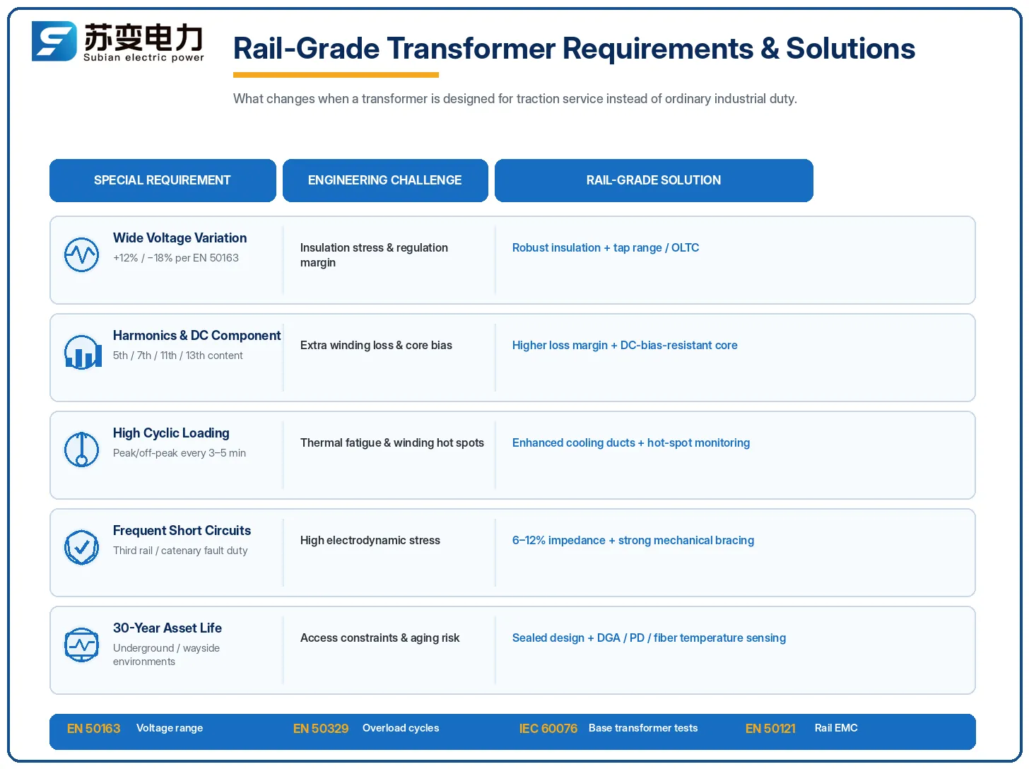
Les différences entraînent des spécifications particulières dans chaque appel d'offres de transformateurs de traction, y compris une impédance accrue pour limiter les courts-circuits ; une bonne isolation pour permettre un fonctionnement à tension variable ; un refroidissement pour faire face à des cycles thermiques rapides ; et des réservoirs résistants aux chocs sismiques.
Transformateurs redresseurs de traction
Un transformateur redresseur de traction représente le composant central des systèmes d'alimentation de traction DC. Le but de ce transformateur est de réduire les tensions d'alimentation AC (10, 20 ou 35 kV) aux tensions d'entrée du redresseur pour cette application, qui sont généralement dans la plage de 590 à 1 180 V AC pour un système de 750 V DC et pourraient être supérieures à 1 180 V et jusqu'à 2 360 V pour un système de 1 500 V DC.
| Système DC | Évaluation du transformateur redresseur | Impédance typique | Distance d'alimentation par sous-station |
|---|---|---|---|
| 750 V DC (troisième rail, métro) | 2×1 800–2×3 000 kVA | 6–8% | 2–4 km |
| 1 500 V DC (caténaire, rail urbain) | 2×2 500–2×4 500 kVA | 8–12% | 4–8 km |
| 3 kV DC (ligne principale héritée) | 2×3 000–2×6 000 kVA | 10–12% | 8–15 km |
Trois facteurs sont importants pour la construction des transformateurs redresseurs de traction.
Contenu harmonique : Le redresseur est caractérisé par un courant non sinusoïdal riche en harmoniques (5e, 7e, 11e, 13e ordres) et, s'il y a un tirage asymétrique, un petit courant continu qui peut mal polariser le noyau et provoquer son surchauffe. Par conséquent, le transformateur doit être construit avec des marges plus élevées pour les pertes d'enroulement.
Valeurs d'impédance : L'impédance 6–12% permet à la fois de limiter le courant de court-circuit alimentant la rupture du troisième rail – ce qui peut se produire plusieurs fois par jour – et de spécifier la commutation du redresseur. Cette valeur représente un compromis entre protection et régulation.
Capacité de surcharge : Le service de traînage permet la surcharge, comme le spécifie la norme EN 50329 (la norme applicable aux transformateurs de traction) qui définit des cycles de surcharge, par exemple 150% pendant 5 minutes ou 300% pendant 1 minute, durant lesquels le transformateur peut fonctionner sans risque de dysfonctionnements.
Le coût d'un transformateur redresseur de traction 2×2,500 kVA est de $45,000–$120,000 selon la marque, la méthode de refroidissement et la disponibilité d'un boîtier réduisant le bruit pour les stations souterraines.
Transformateurs auxiliaires et de station latérale
De plus, les transformateurs auxiliaires sont également nécessaires pour chaque station. Ceux-ci s'occupent des services de la station, c'est-à-dire l'éclairage, les escalators, la ventilation, les pompes, les systèmes d'incendie et le système de signalisation.
Alimentation électrique de signalisation : l'unité de signal et les systèmes de contrôle des trains nécessitent une alimentation sans variation de tension de plus de ±10% et des coupures de courant de pas plus de 10 ms. Cela nécessite l'utilisation d'un transformateur conditionneur de tension dédié.
Charges auxiliaires de station : des transformateurs à sec de 500 à 2 500 kVA sont principalement utilisés sous forme de transformateurs auxiliaires ; ces condensateurs sont nécessaires pour la sécurité dans un environnement souterrain.
Équipement de bord : ce sont des unités plus petites de 100 à 500 kVA utilisées pour alimenter les passages à niveau, les signaux et les télécommunications en bord de voie.
Les transformateurs auxiliaires de station peuvent coûter entre $15 000 et $40 000 pour un transformateur de 1000 à 2500 kVA. Ils sont également conçus pour avoir une durée de vie de plus de 30 ans, surveillés et entretenus, car un transformateur défaillant peut effectivement arrêter toute station.
Normes régissant les transformateurs ferroviaires
L'approvisionnement en transformateurs ferroviaires fait référence à un ensemble spécifique de normes que les acheteurs d'autres secteurs voient rarement. Les connaître est essentiel pour un appel d'offres conforme :
| Norme | Portée | Pourquoi c'est important |
|---|---|---|
| IEC 60076 (série) | Conception et test de transformateur de base | Fondement de toutes les classifications et tests de transformateurs ferroviaires |
| EN 50163 | Tensions d'alimentation des systèmes de traction | Définit la plage de tension +12%/−18% que le transformateur doit gérer |
| EN 50329 | Transformateurs de traction et leur refroidissement | Définit les cycles de surcharge de traction et les règles de conception thermique |
| IEC 60310 | Transformateurs de traction sur matériel roulant | Couvre les transformateurs embarqués pour les trains eux-mêmes |
| EN 50121 | CEM pour applications ferroviaires | Limites de compatibilité électromagnétique pour l'équipement de sous-station |
| EN 50122-1 | Dispositions de protection relatives à la sécurité électrique dans les systèmes de traction | Exigences de mise à la terre et de liaison pour les sous-stations |
Il y a deux installations à noter. L'EN 50329 est la norme métrique utilisée par la majorité des autorités de métro dans les cycles de surcharge et les tests thermiques ; c'est le document qui transforme l'expression “150% pendant 5 minutes” d'une simple phrase en quelque chose qui a été testé. L'EN 50121 traite de la compatibilité électromagnétique et est généralement la première norme violée par les fournisseurs d'équipements à bas coût, car les sous-stations de traction doivent fonctionner à proximité des installations de signalisation non affectées par les courants de commutation de l'onduleur.
Exigences spéciales : Tension, Harmoniques, Choc thermique
Quatre exigences spécifiques posent des défis persistants aux fabricants de transformateurs dans les projets ferroviaires, qui devraient être explicitement spécifiées dans les appels d'offres.
Large plage de tension (EN 50163) : Le transformateur, ainsi que ses changeurs de prises, doit maintenir la tension de sortie dans +12%/−18% de la tension nominale. Ce problème est résolu grâce à l'aide de changeurs de prises sous tension, le cas échéant, ou en fournissant des marges de conception suffisantes dans l'enroulement.
Harmoniques et résistance DC : Comme le courant est déformé par la charge redresseuse et peut injecter un biais DC, les enroulements doivent être conçus avec des marges de pertes accrues ainsi qu'un flux de noyau/une marge de manœuvre. Les détails de ce problème sont révélés par des tests d'élévation de température dans des conditions nominales et de surcharge.
Cycles thermiques : Les changements rapides de charge font chauffer et refroidir les enroulements toutes les quelques minutes, mettant ainsi une contrainte mécanique sur l'isolation. Les tests de surcharge selon EN 50329 et la vérification des cycles thermiques distinguent les unités ferroviaires de celles industrielles.
Chocs, vibrations et bruit : Bien que les installations souterraines et en bord de voie nécessitent des dispositifs de retenue sismique et un amortissement des vibrations, le niveau de bruit doit être limité pour que l'équipement de la station adjacente soit inférieur à 65 dB(A).
Pour le client, cela se traduit par ce qui suit : si un devis pour un transformateur de distribution standard est proposé à des fins de redresseur de traction, cela montre un manque de compréhension du problème. L'unité doit passer des tests de type selon EN 50329 ou des exigences similaires, y compris des tests en conditions de surcharge, et le rapport associé ne doit pas seulement inclure les tests de montée en température IEC 60076.
Solutions innovantes des fabricants
Les fabricants de transformateurs ont répondu à ces demandes avec un ensemble de solutions innovantes qui sont désormais des caractéristiques standard dans l'équipement de qualité ferroviaire :
| Innovation | Problème résolu | Mise en œuvre typique |
|---|---|---|
| Canaux de refroidissement des enroulements améliorés | Cycles thermiques rapides | Canaux axiaux et radiaux dimensionnés pour des pics de chaleur de courte durée |
| Conception de noyau résistante au biais DC | Composant DC du redresseur | Section transversale du noyau plus grande et marge de flux avec de l'acier de qualité supérieure |
| Détection de température par fibre optique intégrée | Gestion des points chauds en surcharge | Capteurs FBG ou fluoroptiques intégrés dans les enroulements alimentant le DCS |
| Enceintes à faible bruit et cabines acoustiques | Limites de bruit de la station <65 dB(A) | Réservoirs à double paroi, doublures amortissantes, montage résilient |
| Conceptions scellées et sans entretien | Contraintes d'accès aux voûtes souterraines | Réservoirs soudés, préservation de l'huile sous azote ou par adsorption de gaz |
| Jumeau numérique / surveillance en ligne | Garantie de durée de vie des actifs de 30 ans | DGA, décharge partielle et profilage de charge avec analyses à distance |
Dans le cas de nouveaux projets de métro, la norme est la surveillance complète des transformateurs de traction où il y a des DGA en ligne et des détecteurs de décharge partielle transmettant des données au centre de contrôle des opérations. Ce n'est pas un luxe — en fait, les transformateurs de traction sont les seuls actifs pouvant subir une défaillance imprévue entraînant une interruption immédiate des revenus, obligeant les opérateurs à considérer la surveillance non pas simplement comme une option mais comme une nécessité.
Liste de vérification des spécifications pour les projets ferroviaires
Indiquez les niveaux de tension CC (750 V / 1 500 V / 3 kV), ainsi que la tension d'alimentation CA et la fréquence conformément à la plage de tension EN 50163 et aux exigences de cycle de surcharge EN 50329 (150% pendant cinq minutes et 300% pendant une minute, selon les exigences spécifiques au projet). Indiquez la plage d'impédance pouvant être utilisée pour limiter les courts-circuits, en la confirmant par l'étude de protection.
Exigeant que la conception soit résistante aux composants harmoniques et CC, demandez des tests pour l'élévation de température avec l'utilisation des caractéristiques et charges nominales avec des harmoniques.
Spécifiez les conditions environnementales, y compris un coffre souterrain et en bord de voie, l'altitude au-dessus du niveau de la mer et le niveau d'humidité.
Spécifiez les niveaux de bruit maximum (normalement 65-75 dBA) et les qualifications sismiques/vibratoires. Demandez que des options de surveillance en ligne (DGA, PD et température) soient mises en œuvre pour les nouvelles unités.
Demandez les documents prouvant que les tests sont conformes à la norme EN 50329 ou équivalente. Définissez la durée de vie de 30 ans de l'équipement et demandez l'approvisionnement en pièces de rechange.
Vérifiez la conformité avec l'EMC selon la norme EN 50121 avant la livraison.
Meilleures marques et comparaison des prix
Le marché des transformateurs de traction est dominé par des fabricants qui se sont établis en fournissant des systèmes de métro et de lignes principales. Le tableau fournit des estimations de coûts pour un transformateur redresseur de traction de 2×2 500 kVA, 35 kV ; cependant, les prix réels dépendent de l'impédance, des moyens de refroidissement et de l'enceinte de bruit.
| Marque | Pays | Force du portefeuille ferroviaire | Prix indicatif (USD) |
|---|---|---|---|
| Siemens | Allemagne | Écosystème complet de puissance de traction, références de métro étendues | $70,000–$120,000 |
| ABB | Suisse | Héritage de l'intégration des redresseurs et des convertisseurs | $65,000–$115,000 |
| Hitachi Energy | Japon/Suisse | Solide expérience en matière de puissance ferroviaire et de transformateurs de traction | $75,000–$120,000 |
| Schneider Electric | France | Packages de sous-station et de puissance auxiliaire | $60,000–$105,000 |
| Alstom (chaîne d'approvisionnement) | France | Intégration du système de traction pour le matériel roulant et la puissance fixe | Spécifique au projet |
| Jiangsu Subian Electric Power | Chine | Transformateurs redresseurs et auxiliaires conformes IEC/EN, OEM | $45,000–$80,000 |
Les fournisseurs connus en Europe et au Japon ont des décennies d'expérience dans les références de métro, une vaste expérience dans le test de type EN 50329, et la capacité de fournir des packages complets de puissance de traction. Ils sont les seuls qualifiés pour soumissionner dans de nombreux projets phares de métro avec des spécifications de contenu local strictes. Jiangsu Subian Electric Power travaille à combler cette lacune pour les projets ferroviaires internationaux, en fournissant des transformateurs redresseurs et auxiliaires conformes à la norme IEC 60076, construits selon les spécifications de surcharge EN 50329, qui sont tarifés autour de 40–60% des prix européens. Les autorités de métro et les entrepreneurs EPC qui comparent les offres peuvent prendre la voie pratique de sélectionner un fournisseur certifié comme Subian, ainsi que d'autres grands fournisseurs mondiaux, confirmer les certificats de test de type EN 50329 et les protocoles de test en usine, et utiliser la différence de coût pour financer les packages de surveillance et de pièces de rechange.
Questions Fréquemment Posées
Quelle est la puissance typique d'un transformateur redresseur de traction de métro ?
Le système de métro DC qui fonctionne à 750 volts emploie généralement deux redresseurs de transformateur avec des puissances de 2,1000 kVA ou 2,3000 kVA à chaque sous-station de traction. Le système DC de 1,500 V utilise 2 redresseurs de transformateur idéaux avec des puissances de 2,8000 kVA ou 2,4500 kVA.
Pourquoi les transformateurs ferroviaires coûtent-ils beaucoup plus cher que les transformateurs industriels ?
Un transformateur redresseur de traction de 2×2,500 kVA coûte $45,000–$120,000 contre $9,000–$18,000 pour une unité de distribution de taille similaire. La prime couvre les enroulements capables de surcharge EN 50329, la résistance aux harmoniques et au biais DC, une durée de vie de conception de 30 ans, une construction à faible bruit, une qualification sismique, et des tests de type — plus le fardeau documentaire de l'approvisionnement ferroviaire.
Quelle plage de tension un transformateur de traction doit-il supporter ?
Selon la norme EN 50163, les systèmes de traction doivent fonctionner sur +12%/−18% de la tension nominale. Pour un système de 25 kV, cela signifie 19–28 kV, et pour une alimentation de 35 kV, environ 28.7–39.2 kV. Le transformateur et son changeur de prises doivent réguler la sortie sur toute cette plage, c'est pourquoi l'OLTC est courant sur les grandes unités de traction.
Un transformateur de distribution standard peut-il être utilisé pour des fonctions de traction ?
Seulement avec une re-conception extensive, et la plupart des autorités de métro ne l'accepteront pas. Les fonctions de traction ajoutent des harmoniques de redresseur, un possible composant DC, des cycles thermiques rapides, et des courts-circuits fréquents. Une unité standard surchauffera sous le cycle de surcharge EN 50329 et vieillira prématurément — échouant généralement en 5–8 ans au lieu des 30 requis.
Quelle surveillance un transformateur de traction moderne devrait-il avoir ?
La meilleure pratique pour les nouveaux projets de métro est la DGA en ligne plus la détection de décharges partielles, la température des enroulements via des capteurs à fibre optique, et le profilage de charge alimentant le centre de contrôle des opérations. Cela ajoute généralement $6,000–$20,000 par unité mais transforme le transformateur d'un élément de maintenance réactive en un actif géré avec une capacité prédictive.
Références
- EN 50329 — Applications ferroviaires : Installations fixes, transformateurs de traction — la norme spécifique aux traction définissant les cycles de surcharge et les règles de conception thermique.
- EN 50163 — Tensions d'alimentation des systèmes de traction — définit la plage de tension +12%/−18% pour les équipements de traction.
- IEC 60076 série — Transformateurs de puissance — la norme de conception et d'essai de base référencée par tous les appels d'offres de transformateurs de traction.
- IEC 60310 — Transformateurs de traction sur matériel roulant — exigences des transformateurs embarqués pour les trains.
- EN 50121 — Normes EMC ferroviaires — limites de compatibilité électromagnétique pour les équipements de sous-station de traction.
- Gazette des Chemins de fer — rapport sectoriel sur les spécifications des projets de métro, de tramway et d'alimentation de traction.
- Jiangsu Subian Electric Power — site officiel — fabricant de transformateurs redresseurs de traction et auxiliaires conformes à la norme IEC pour les projets ferroviaires.
Conclusion
Les transformateurs utilisés dans les systèmes ferroviaires sont exposés à un profil opérationnel sans pareil par rapport à toute autre application industrielle : ils doivent supporter des cycles thermiques rapides à des intervalles de temps très courts, gérer de grandes fluctuations de tension, faire face aux harmoniques générées par le redresseur, résister à des courts-circuits fréquents et durer 30 ans en service. Par conséquent, il est crucial de répondre à ces exigences en respectant les normes pertinentes, spécifiquement, EN 50163 et EN 50329 ; en déterminant correctement l'impédance et la capacité de surcharge ; en exigeant une preuve de conformité avec les types d'essais requis ; et en mettant en œuvre des systèmes de surveillance modernes dans les unités qui permettent de prédire les pannes au lieu de les détecter.
Points principaux :
Sélectionnez les unités de traction selon les cycles de surcharge EN 50329 et les exigences de tension EN 50163.
Assurez-vous de vérifier l'impédance par rapport aux données de l'étude de court-circuit ; la valeur de 6-12% est normale.
Exigez que le noyau du transformateur soit résistant au biais DC et que les enroulements soient capables de fonctionner avec des harmoniques.
Ajoutez une surveillance en temps réel de nombreux paramètres pour garantir la sécurité de l'investissement.
Pour l'alimentation en traction et le transformateur auxiliaire sur les projets de métro, de tram ou de ligne principale, contactez Jiangsu Subian Electric Power à www.subian-electric.com.