


이더넷 데이터 포트는 기본적으로 변압기가 부착된 두 개의 선으로 구성됩니다. 사무실 환경에서는 변압기가 “추가된” 단계이지만, 변전소 내부에서는 ETH 네트워크의 단락이 스위치의 치명적인 고장을 일으키는 것을 방지하는 유일한 장치입니다(스위치 고장 비용이 단락 자체보다 더 큽니다). 절연은 산업용 데이터 케이블링의 가장 두드러지지 않는 특성이지만, 가장 중요한 특성이기도 합니다.
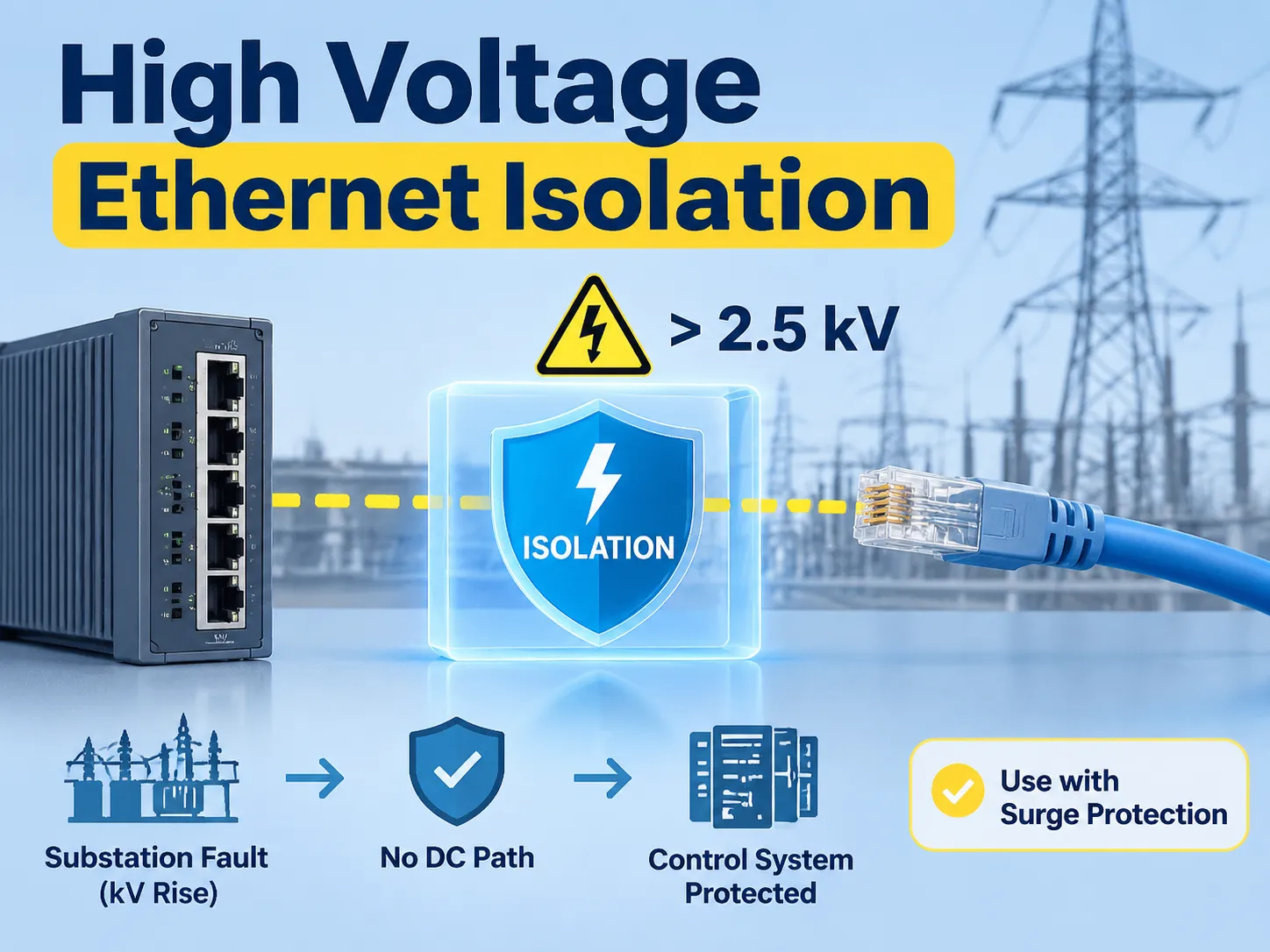
간단한 답변: 고전압 이더넷 절연은 구리 포트가 케이블과 갈바닉 분리되어 있음을 의미합니다. 결과적으로 장비에서 반대편까지 DC 경로가 존재하지 않습니다. 표준 이더넷 자기 부품은 1.5 kV에서 작동하며, 산업용 절연기는 2.5 kV, 강화 절연기는 5 kV 이상에서 작동합니다. 이는 변전소에서 고장 시 수 킬로볼트에 달하는 접지 전위 상승 때문에 전력 설비에 매우 중요합니다(절연이 없으면 절연되지 않은 포트가 DC 경로로 사용될 수 있어 접지 전위 상승이 제어 시스템으로 전달될 수 있습니다). 절연은 서지 보호와 다르며, 절연은 연속적인 전위 차이를 차단하는 반면 서지 장치는 일시적인 이벤트를 차단합니다. 적절한 설치에서는 절연과 서지 보호가 함께 사용됩니다.
다음 섹션에서는 이더넷 데이터 케이블에서 절연이 무엇을 포함하는지, 변전소가 구리 배선에 적합하지 않은 환경인 이유, 접지 전위 상승 계산, 절연 변압기에 포함된 내용, 절연 변압기 등급, 절연과 서지 보호의 차이, 애플리케이션에 가장 적합한 옵션 결정 방법, 전력 프로젝트에서 절연이 나타나는 위치, 절연 등급 비교, 그리고 당사 자체 변압기 개발이 어떻게 적합한지에 대한 정보를 포함합니다.
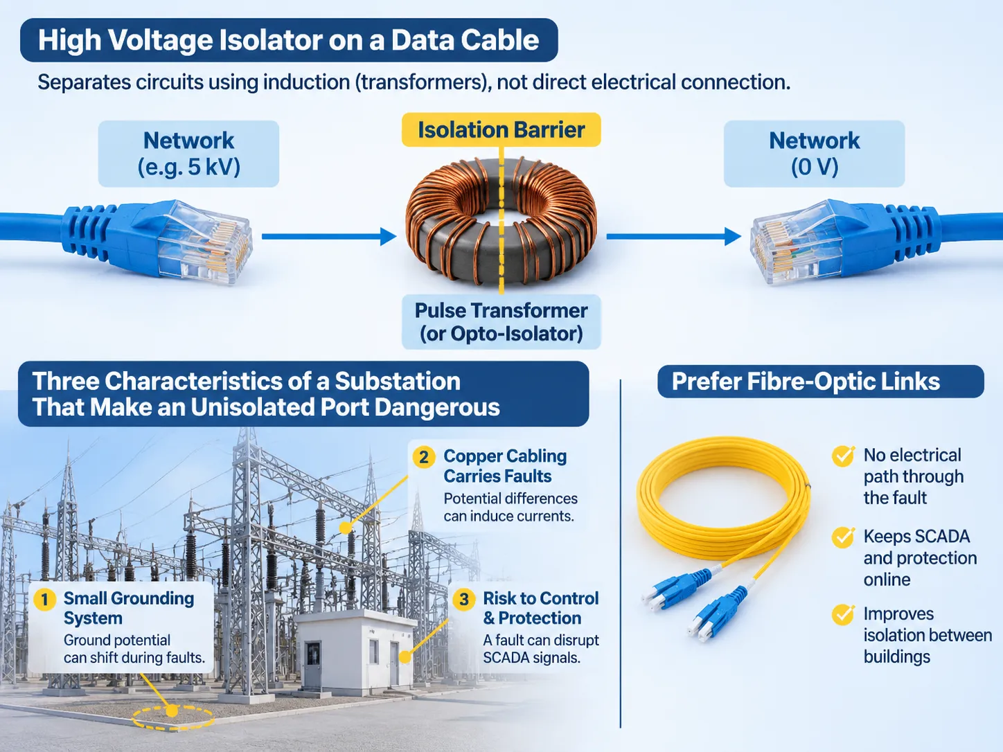
데이터 케이블에서 고전압 절연기가 작동하는 방식
절연기는 전기 회로를 분리하여 두 회로 간 직접적인 통신 경로를 허용하지 않습니다. 이는 전기 와이어를 통한 전자 흐름 대신 유도 또는 광(광자) 전송을 사용하여 달성됩니다. 이더넷 포트와 같은 경우, 이 절연 장벽은 토로이달 또는 팟 코어에 배치된 작은 펄스 변압기(각 와이어 쌍마다 하나의 변압기) 형태를 취하며, 1차(입력) 및 2차(출력) 권선은 절연체로 분리되어 있습니다.
이 변압기들은 두 측이 서로 다른 전기 전위를 가질 수 있도록 하면서도 그 사이의 절연을 유지합니다; 이 특성은 두 건물에 위치한 장비에 데이터 네트워크를 연결할 때 유용하며, 두 건물의 접지 전위가 동일하지 않을 수 있습니다. 한 건물의 데이터 네트워크는 5 kV에 있을 수 있고, 다른 건물의 데이터 네트워크는 0볼트일 수 있습니다.
전력 변압기에 사용되는 절연 장벽은 다음과 같은 원리로 작동합니다 작업자 보호를 위한 절연 변압기와 전기 충격 위험으로부터 재산을 보호하는 절연 변압기입니다.
절연되지 않은 포트를 위험하게 만드는 변전소의 세 가지 특성
변전소의 주요 특성 중 하나는 최대 고장 전류 용량보다 훨씬 작은 접지 시스템의 설치입니다. 따라서 고장 상태에서는 고장 전류가 높기 때문에 접지 시스템이 접지 전위에 대해 이동하게 됩니다.
구리 배선은 일반적으로 스위치야드에서 제어 건물 및 보호 패널까지 연결되며, 이는 케이블 실드에서 전위 차이를 전류로 변환하는 기하학적 구조를 만듭니다. 변전소 제어 및 보호 시스템은 고장 발생 시에도 정상적으로 작동해야 합니다. 고장이 네트워크 스위치를 중단시키면 SCADA 링크와 보호 신호가 가장 필요할 때 끊기게 됩니다. 환경에 적합하지 않은 40센트짜리 변압기 고장이 이 문제를 야기합니다.
변전소 자동화 및 유틸리티 관행은 건물 간 연결에 광섬유 케이블을 사용하고, 국부적으로는 절연된 구리 케이블을 사용하는 것을 권장합니다. 이는 단순히 더 높은 품질의 신호를 생성하기 위한 것이 아니라, 변전소 야드 내에서 고장이 발생해도 Cat6 케이블을 통해 제어실로 전파되지 않도록 하기 위함입니다.
접지 전위 상승 수치
고장 전류가 그리드를 통해 접지로 주입될 때, 고장 지점 주변의 지반은 전류량과 접지(그리드)의 저항에 따라 접지 전위가 상승합니다. 예를 들어, 0.5옴의 저항을 가진 그리드에 20 kA의 고장 전류가 들어가면 고장 지점에서 10 kV의 접지 전위 상승이 발생하며, 이 전위는 거리 증가에 따라 감소합니다. 이 수치는 대형 송전 전압의 최대값이 아닌 전송 변전소의 일반적인 값입니다. 따라서 고장 시 10미터 떨어진 두 전기 장치 간의 전위 차이는 킬로볼트 범위일 수 있으며, 이 장치들을 연결하는 도체는 전위 차이를 도체 임피던스로 나눈 전류를 운반합니다. 도체의 예로는 양쪽 끝이 접지된 케이블 실드와 접지되지 않은 포트를 가진 데이터 케이블이 있습니다.
전력 분야에서 변압기 권선은 절연 한계를 나타내며,.
전력 변압기와 배전 변압기의 구분은 해당 비교에서 설명됩니다. 반면 데이터 측면에서는 유사하지만 더 작은 크기의 절연 경계가 있으며, 절연이 필요한 물리적 현상은 또 다른 절연의 필요성도 만듭니다. 이더넷 절연 변압기 내부.
이더넷 절연 변압기
방법 이더넷 절연 변압기 이더넷 케이블링 시스템의 데이터 측과 전원 측 사이에 절연을 제공하기 위해 사용되는 소형 펄스 변압기입니다. 변압기는 네 개의 권선을 가지고 있으며, 각 권선은 1000BASE-T 이더넷 연결에 사용되는 한 쌍의 와이어에 해당합니다. 변압기는 또한 1:1 권수비와 전력 공급용 이더넷(PoE) 목적의 케이블 측 중앙 탭을 가지고 있습니다. 변압기는 케이블링 시스템의 데이터 측에서 오는 차동 신호(수백 밀리볼트에서 약 2볼트 피크 투 피크)를 통과시키면서, 양 도체 모두에 존재할 수 있는 공통 모드 전압의 통과를 방지합니다.
변압기의 1차 및 2차 권선을 분리하는 절연체는 유전체 장벽이며, 이 절연체의 두께와 보빈 및 포팅 화합물을 통한 크리피지 거리(표면 누설 거리)가 변압기 절연의 전압 등급을 결정합니다. 1.5 kV 등급의 부품은 이 전압에서 1분간의 테스트를 거쳤으며, 이는 서지 전압 및 동작 전압 테스트와는 별개입니다.
변압기가 차단할 수 있는 한계가 있습니다. 변압기의 1차 및 2차 권선은 각각 수십 피코패럿의 정전 용량을 가진 커패시터로 분리되어 있으며, 이 정전 용량은 빠른 과도 신호의 통과를 허용합니다. 1.2/50 마이크로초 파형과 나노초 상승 시간을 가진 서지는 절연 장벽을 단락시키고 과도 신호가 장치를 통해 PHY로 전달되도록 하므로, 절연기 앞에 클램핑 장치를 설치해야 합니다.
절연 기능을 제공하는 것 외에도, 변압기는 신호 대역을 통과시키고 다른 모든 대역을 차단하는 필터 역할도 합니다. 자기 모듈에 공통 모드 인덕터를 추가하고, 교체 부품이 부적절하게 선택될 때 비트 오류율이 상승하는 것은 신호 무결성이 적절한 선택에 달려 있음을 보여줍니다.
변압기 개발에 사용되는 구조 논리는 전력 변압기와 유사합니다. 고체 절연체 적용과 제어된 크리피지 거리는 금속 인클로저 두께가 아닌 등급을 정의하는 데 사용됩니다. 이 접근법은 12 kV 및 24 kV에서 구현되며, 건식 배전 변압기 범위, 에 적용되지만, 이러한 응용에는 추가 변수가 존재합니다.
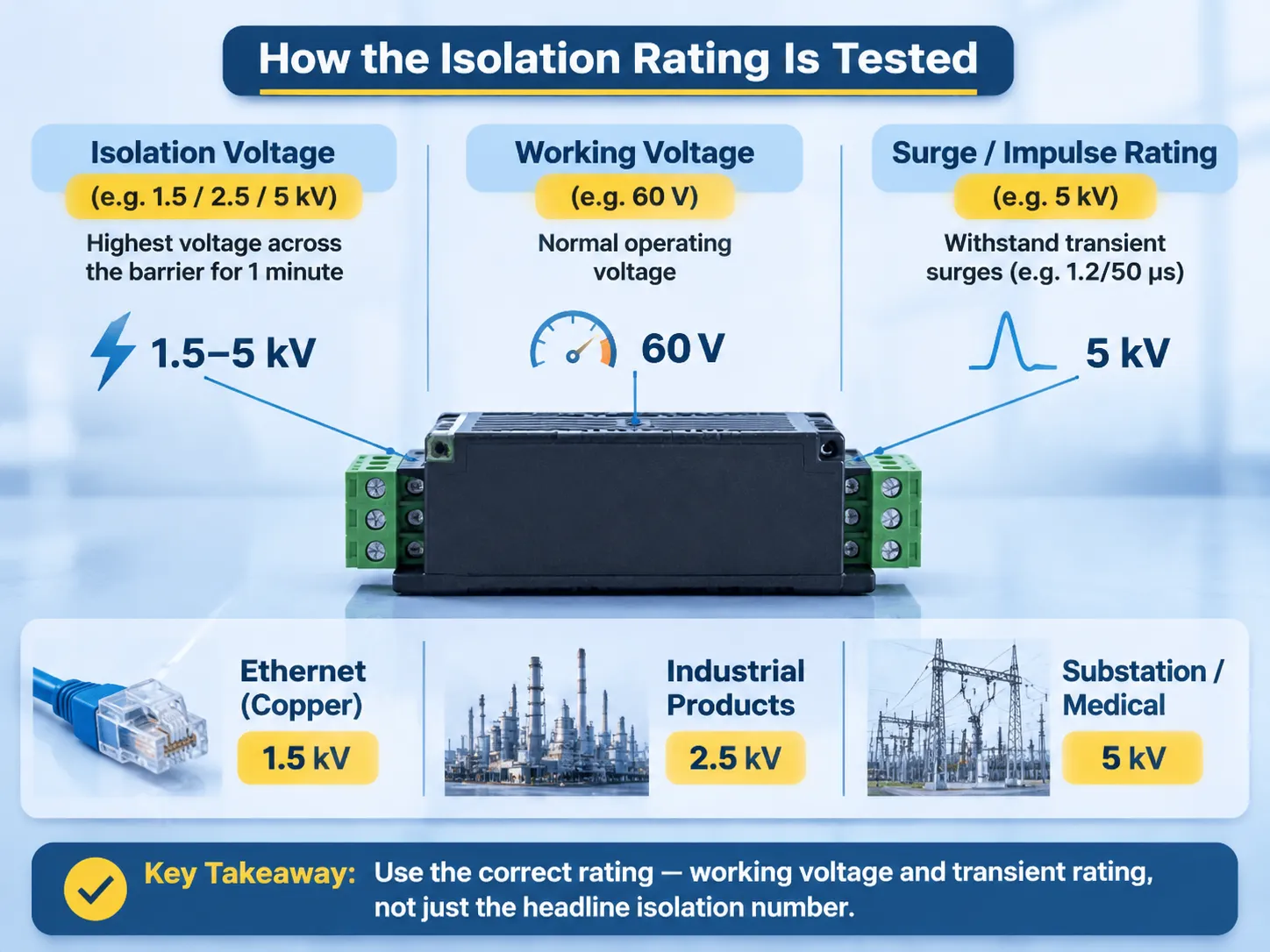
절연 등급 테스트 방법
격리 등급은 각 격리기 데이터 시트에 세 개의 숫자가 나타나기 때문에 혼란스러울 수 있습니다. 격리 전압 시험은 입력과 출력 사이의 장벽에 대해 지정된 시간(보통 1.5, 2.5 또는 5 kV에서 1분) 동안의 최고 전압으로, 장벽의 동작 전압 등급과 비교할 수 없으며 교환할 수도 없습니다. 동작 전압 등급은 정상 작동 조건에서 장벽이 견디도록 설계된 장벽의 입력 및 출력 단자 간의 전위차로, 격리 전압 등급보다 훨씬 낮습니다. 장벽의 서지 또는 임펄스 등급은 장벽이 파손 없이 견딜 수 있는 과도 전압을 나타내며, 파형과 피크 값으로 표현됩니다.
구리 이더넷 표준은 구리 인터페이스에 대해 1,500 V의 격리 등급을 요구하며, 이는 장비가 동일 건물 내에 위치하고 동일 접지점을 공유하는 대부분의 설치에 충분합니다. 산업용 제품은 2.5 kV 등급이 있으며, 변전소 또는 의료용 제품은 적절한 제품 안전 표준에 따라 강화 절연.
전력 설치 등급을 결정할 때는 동작 전압과 과도 등급(60 V 동작 전압; 5 kV 1분 등급)만 중요하므로, 5 kV 1분 등급 제품은 킬로볼트 전위차가 있는 두 건물을 연결하는 장치가 아니라 국부 장벽으로만 간주해야 합니다. 이 범주의 제품에서 가장 흔한 사양 오류는 헤드라인 숫자입니다.
격리는 서지 보호가 아닙니다.
격리는 장기간 동안 전위차 발생을 방지하며, 서지 보호는 매우 짧은 시간(마이크로초) 동안 지속되는 과도 전위로부터 보호합니다. 격리와 서지 보호는 근본적으로 다르며 서로 대체할 수 없습니다.
서지 보호가 없는 격리기는 격리기의 권선 간 정전 용량을 통해 과도 전압이 통과하여 PHY에 스트레스를 유발합니다. 격리기가 없는 서지 보호기는 서지로부터 격리를 제공하지만, 케이블 스크린 연결의 연속성으로 인해 케이블 스크린 양 끝에 지속적인 전위차가 존재하여 포트에서 단락 상태를 만듭니다. 변전소에서 서지 보호와 격리는 함께 사용해야 하며, 순서가 중요합니다. 서지 보호는 항상 케이블 진입부에 배치되고 격리는 그 뒤에 위치하여 격리 장벽의 우회를 방지해야 합니다. 두 경우 모두 필요한 최종 장비는 접지 연결입니다.
절연이 작동하려면 절연 장벽의 양쪽 끝에 별도의 접지 연결이 있어야 하며, 케이블 스크린이 있는 케이블의 양쪽 끝에 스크린이 연결되어서는 안 됩니다. 만약 연결되어 있다면 절연이 이루어지지 않습니다. 양쪽 끝에 접지된 스크린 쌍이 있다면, 스크린 케이블이 절연 장벽을 우회하는 경로를 제공하므로 절연기는 아무 기능도 수행하지 않습니다.
구리, 광섬유 또는 절연 구리
두 위치 간의 전위차가 있는 링크 매체로 구리, 광섬유 또는 절연 구리를 선택하는 기준은 거리, 가격 및 예상 전압 차이에 따라 결정됩니다.
광섬유는 전도성 매체를 포함하지 않기 때문에 전도 경로를 완전히 제거하는 유일한 매체입니다. 그러나 포트당 비용이 구리 매체보다 높고, 양쪽 끝에 미디어 컨버터 또는 광섬유 포트가 필요하며, 이더넷을 통한 전력 공급이 불가능합니다. 변전소와 제어 건물 간 또는 건물 간 연결 시, 광섬유는 전력 산업에서 가장 일반적으로 사용되는 매체입니다.
절연 구리는 구리 케이블의 Cat6 배선 및 이더넷 전력 공급 기능을 유지하면서 예상 전압 차이에 대해 정격 장벽을 추가한 중간 솔루션입니다. 절연 구리는 일반적으로 동일 건물 내 다른 접지 바에 연결된 패널이나 중간 수준의 고장 전류가 예상되는 경우에 가장 적합한 옵션입니다.
일반 구리는 공통 접지가 있는 캐비닛 또는 실내 연결에 적합한 매체입니다. 그 외 모든 응용 분야에서는 광섬유 또는 절연 구리를 사용해야 합니다.
전력 프로젝트에서 장벽이 나타나는 위치
아래 표는 전력 분배 프로젝트 내에서 장벽의 설치 구성을 설명하며, 설계 검토에 포함될 버전입니다.
| Link | Barrier | 이유 |
|---|---|---|
| Within the protection panel | None beyond the PHY magnetics | Same earth, short run |
| Between panels in a control room | 2.5 kV isolated copper | Different earth bars, shared room |
| Control building to switchyard | Fibre | Ground potential rise during a fault |
| Between two buildings | Fibre, or isolated copper with a surge device | Separate earths, long copper run |
| Substation to control centre | Fibre | Distance plus potential difference |
| Field device to marshalling cabinet | Isolated copper or fibre per the standard | Exposed route, outdoor equipment |
| Camera or access control on a pole | Isolated copper plus surge protection | PoE needed, lightning exposure high |
Of the above, the third row utilizes the “most stringent” requirement that utilities enforce, namely that a copper link from the control building into the yard carries the potential for the yard to earth into the control room, where the protection relays are located, regardless of how many isolation ratings may be assigned to a device/component.
Comparison of Ratings
The table below compares the three product classes to each other. The values shown are typical, not universal. The applicable product safety standard determines the reinforced rating.
| 클래스 | Isolation test | 일반적인 사용 |
|---|---|---|
| Standard Ethernet magnetics | 1.5 kV for one minute | Office equipment on the same earth; working voltage typically up to a few tens of volts |
| Industrial isolator | 2.5 kV | Panels and machines; different earth bars and medium voltage power systems, with longer conductor runs |
| Reinforced isolator | 5 kV or higher | Substations, medical applications, hazardous areas; most commonly used at system voltages up to and including 1 kV |
When comparing equipment, the voltage rating is not the number to use. A 400 V system may experience a 10 kV differential at a data port during an electrical fault, so the isolation class should be derived from the fault study and not from the nominal voltage. The voltage classification of distribution transformers correlates to the insulation levels assigned to each system voltage, as the data barrier and power barrier are designed to withstand the same fault current.
Where SUBIAN Sits
SUBIAN does not manufacture network isolators; we manufacture the devices that deliver earth rise potential during faults: transformers and substations governing ground potential rise, and hence, the isolation requirements of a data link.
The relationship between our devices and network isolators is much more complex than it appears. A network that incorporates transformers utilising particular vector groups and earthing methods defines the ground potential rise in the control building and will inform the network design. For example, if a transformer incorporates a delta primary and an earthed star secondary, it will have a significantly different ground potential rise profile than a transformer that has a solidly earthed neutral; the isolation rating of the Ethernet port located two rooms away will reflect these differences.
A range of power line transformers has been identified in order to document these earthing decisions, and information specific to dry-type transformers used indoors and outdoors is documented separately due to the difference in earth path.
With a data isolation inquiry, we are able to provide the fault current and the earth connection type; however, we are unable to provide the isolator itself. While we could reference an isolator manufactured by another company, it is much more beneficial to let you know that we do not manufacture the isolator, rather than supplying an uncertain reference of a device.
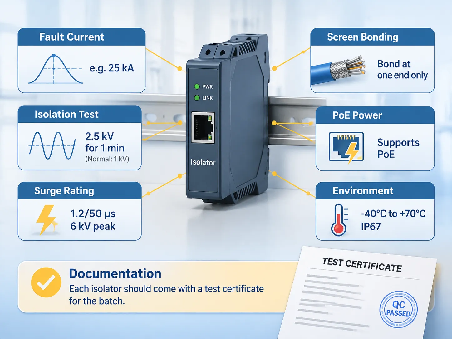
사양 체크리스트
The data isolation specification needs to include the following six items:
- The anticipated fault current for the circuit being isolated. This information should be obtained from your fault current study and not from an estimate.
- Isolation testing voltage and duration, with identification of both the isolation test voltage and isolation test duration, as well as the normal working voltage for the equipment being isolated.
- The surge rating of the isolator, with information regarding the waveform and peak values.
- The method of screen bonding for the isolator. If the screen is bonded at both ends, the effectiveness of the isolator is lost.
- The power requirements for Power-over-Ethernet operation, to ensure the isolator does not add to the insertion loss for the power.
- The minimum and maximum ambient temperatures, along with ingress requirements for the enclosure.
When it comes to documentation, each isolator should be sold with a test certificate indicating the rating of each isolator in the same batch as a manufacturer’s statement, and a supplier who cannot provide a test certificate for every unit sold in the batch is selling a product based on an unverified number.
자주 묻는 질문
What Do We Mean by High Voltage Isolation?
High voltage isolation is the barrier between two electrical circuits that provides a means for energy to pass through but does not provide a conductive path (common reference point) so that each side of the barrier can remain on a different voltage potential. Ethernet uses a pulse transformer designed to work with voltages from 1.5 kV to 5 kV or greater, while in power systems it is a transformer winding that connects the high-voltage and low-voltage networks.
What Is the Function of Ethernet Isolators?
Ethernet isolators produce a galvanic block in the copper data connection that stops current from flowing between the two ends of the cable with a potential difference. They also block ground loops at low frequencies and transfer signal through inductive coupling.
How Much Voltage Can Ethernet Carry?
The actual signal being transmitted is roughly 2 V peak to peak, and Power over Ethernet transmits power voltages of 48 V to 57 V d.c. at a maximum of 90 W with the new standard of the day. The isolation rating is a separate dimension, with standard copper being 1.5 kV, typical industrial devices being 2.5 kV, and heavily constructed reinforced types being rated for 5 kV.
Is There an Ethernet Industry Trend Towards Obsolescence?
That’s a resounding no. Ethernet copper continues to evolve with the introduction of 2.5 Gbps and 5 Gb over existing copper wiring; 10GBASE-T is used in data centre applications, and Single Pair Ethernet is destined for use in industrial field devices. What is changing is that fibre is quickly taking over in the case of there being a potential difference, or for distance, making copper impossible, thus the decision made is related to routing and not the protocols finishing up.
Do Ethernet Isolators Protect Against Lightning Strikes?
To a limited degree; the galvanic isolation blocks continuous ground potential, and the isolator’s capacitance passes fast transients but will not stop a lightning surge, hence it is likely that the isolator must also have a clamping device located at the cable entry. In addition, the isolator must be rated for the allowable potential residual let-through rating of the clamping device.
Is It Acceptable to Use a 2.5 kV Interface Isolator in a Substation?
Yes, in some locations inside control rooms, but for installations between control buildings and utility switch yards, it will be impossible due to the elevated DC potential of utility faults, therefore the correct answer for installation standards is “fibre.” The correct selection will be based upon the results of fault studies as opposed to the product class.
참고 문헌
- Siemens Energy — Substation Automation and Communication
- Hitachi Energy — Protection, Control and Substation Networks
- Phoenix Contact — Industrial Ethernet and Surge Protection
- UL Solutions — Isolation and Communication Equipment Certification
- Electrical Engineering Portal — Earthing, Ground Potential Rise and Substation Design
결론
아이솔레이터는 변전소 내에서 발생하는 큰 전위차로 인해 데이터 통신에 상당한 보호를 제공할 수 있습니다. 전위차는 일반적으로 볼트가 아닌 kV 등급으로 정의됩니다.
Copper only in a cabinet, fibre if the cable leaves the building, and isolated copper inside buildings where it is required, with each isolated cable screen connected at only one place.