


While a manufacturing facility may have high-quality switchgear, a properly laid out distribution system, and a correctly sized transformer, a significant piece of equipment could still be out of service due to the inability to find the source of an overcurrent fault that occurred due to a malfunctioning motor-control circuit on a 30kW pumping motor (for example). As such, motor-control-centers (MCCs) were designed as a means to consolidate multiple (dozens/hundreds) motor installations into one area, with individual circuit breakers, overload and fault detection for each motor, while only requiring one bus to connect to the electrical service. This guide will explain the functions of motor control centers, their capabilities, and the requirements contained in the National Electric Code.
In summary, the NEC defines a motor control center (MCC) as a grouping of multiple enclosed sections that share a common power bus, as well as containing various motor controller units. The primary function of an MCC is to allow for the starting, stopping, protecting and monitoring of many motors that operate within a common area. An MCC also serves to provide the following benefits: reduced field wiring; simplified troubleshooting; increased safety (draw-out units); and increased ability to add motor capacity to the plant (addition of ‘buckets’), as opposed to purchasing additional motors. Typically, each motor controller unit will contain a breaker/fuse, contactor and overload relay. At this time, intelligent MCCs possess communication capabilities that are networked and therefore provide a multitude of information to the control system, while controlling the operation of motors.
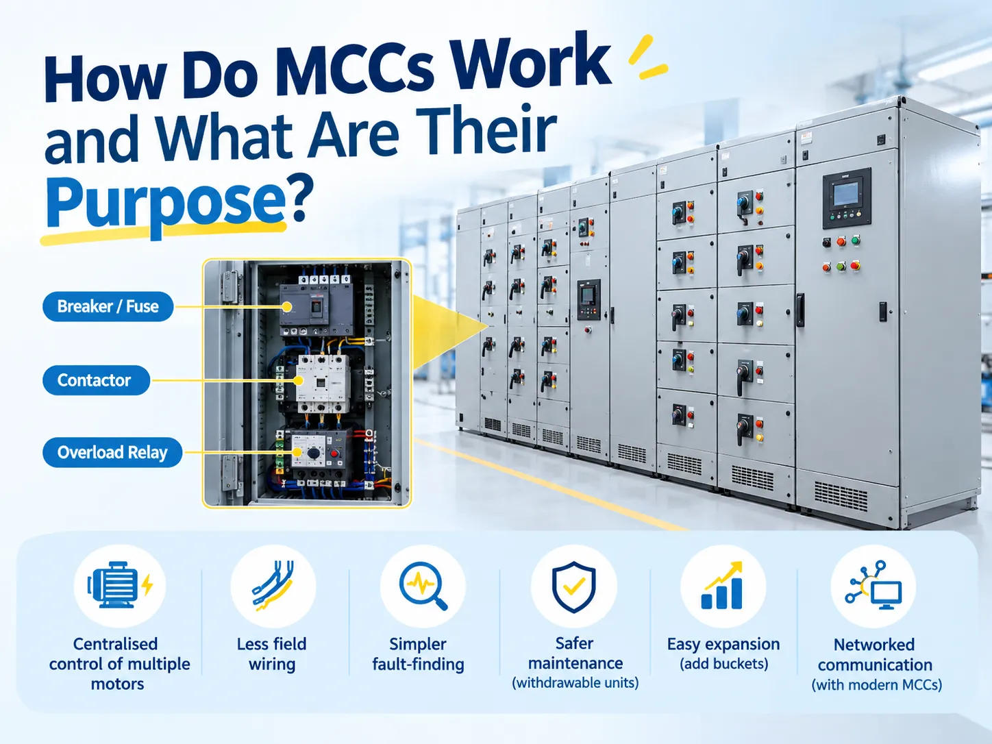
What a motor control center is
The definition according to Article 100 of the National Electrical Code explains an MCC as a collection of enclosed segments with a shared power bus and mainly comprising of motor control devices. The clarity of this explanation is evident in three different places within the text. The term enclosed segments shows that the model is interchangeable because the sections can be assembled together or expanded as per necessity. Shared power bus indicates the presence of a power supply line that connects all sections together rather than a separate line for each section. The third part of the definition specifically mentions motor control units shows that the model is distinct from the panel board and switch board, which are used only in electric distribution.
This design has made MCC a hybrid device, as it has both features of a distribution system and an apparatus. Because of that, it has adopted the ideas of switchboards in terms of the construction specification and also provides additional requirements for the construction of the devices meant for motor circuits, thus making it necessary to have Article 430, Part VIII as an independent piece of writing and not just a part of the articles relating to switchboards.
What an MCC is for: the purposes that justify the cost
An MCC is typically more expensive than the total value of its starters. This premium has six components. Each of which is a valid engineering reason in its own right.
- Centralized control. All motors in a certain area can be turned off and on remotely, making it much easier to resolve any faults. In the event of an offline belt conveyor, the operator knows exactly where to find the starter: in the labeled compartment of an MCC rather than at the machine’s junction box.
- Coordination and selectivity. One setting of the breaking device, applied to the entire bus system, allows for coordination among all electric drives for the effective elimination of electric faults: when one motor is shut down, all other drives can continue running.
- Fewer cables. Distribution and control wires are supplied already wired and tested; all that is needed on-site is to install one main feed wire, special wires for each motor, and a control connection cable.
- Safe maintenance. Replaceable units can be repaired or replaced without cutting power to the whole MCC; this feature is the most important one for process plants.
- Scalability. More motors can be added by plugging new relay boards into the MCC.
- Fault limitation and personnel protection. With the enclosed structure, separators, and arc resistant designs in place, the consequences of the breakdown can be limited to one compartment rather than extending them to the whole room.
The commercial justification of all these advantages is rarely expressed in terms of cost saving but rather as calculated cost of downtime. The workshop suffering from unscheduled shutdowns costing tens of thousands an hour will pay back the cost of an intelligent MCC just by having to spend less time on doing repairs..
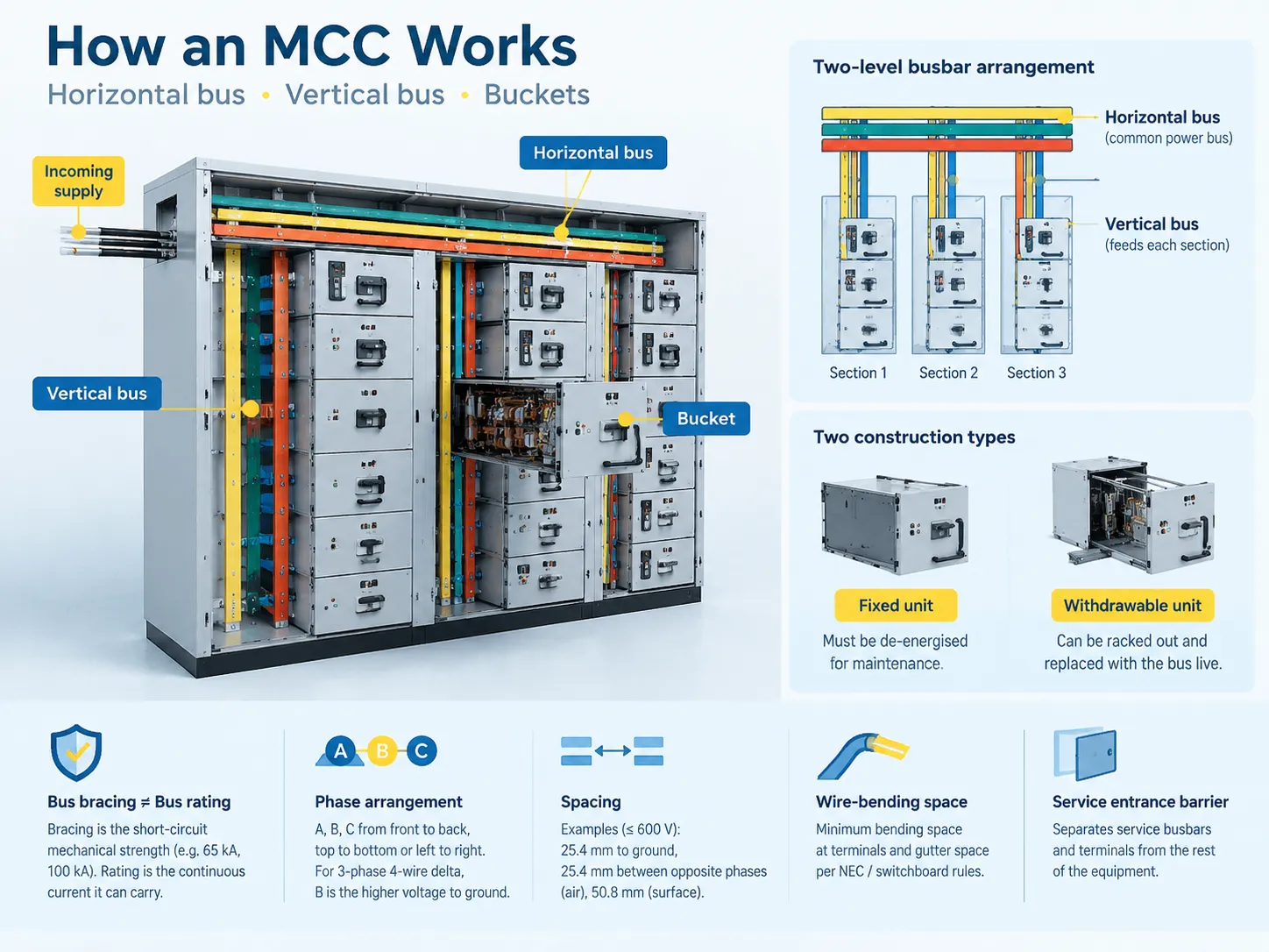
How an MCC works: horizontal bus, vertical bus and buckets
In terms of electricity, an MCC is not complex and in terms of engineering, the engineering design makes it functional. Power flows into the unit and is spread among two levels of busbar. The horizontal bus represents the busbar in the form of a straight bar that connects the power supply wiht all vertical sections of the unit. Within sections, the vertical bus provides power to motor controllers that are placed in this section.
Specifics of construction are based on construction codes and are important to know because they are shown in drawings and regulation documents.
- Bus bracing should not be confused with bus rating. Bus rating means the current capacity of the bus. While bus bracing means the maximum mechanical force that the bus can withstand during a short circuit situation and is expressed in current (for instance, 65 kA or 100 kA). A bus that has sufficient rating and insufficient bracing can be destroyed under fault current.
- Phase arrangement is constant. In a three-phase system, the horizontal and vertical buses should be arranged according to the sequence A, B, C from the front view — that means from the front backward, from the top downward, or from left to right. For a three-phase, four-wire delta circuit, the phase with the higher voltage with ground is called B.
- Spacing is defined by the code. In installations up to 600 V, the spacing table requires 25.4 mm minimum between live bus and the ground, 25.4 mm between opposite phase wires through air and 50.8 mm across surface.
- Wire-bending space is mandatory. The minimum bending space at terminals and gutter space is the same as for switchboards; the reason for this recommendation is that if the conductor is bent outside of the specified bend radius even one time during installation, its insulation can be damaged permanently.
- Barriers separate service busbars from other devices in any service entrance MCC to protect personnel who work in adjacent sections from dangerous situations.
A unit that occupies the place of a vertical section in the MCC is referred to as bucket and this is where electrical work takes place. The interface of the unit with the bus indicates which kind of MCC is used: either a fixed unit or withdrawable one. Fixed means that the unit is bolted to place and cut off from the power supply during maintenance works, while withdrawable one can be withdrawn from the compartment without de-energizing the bus.
What goes inside a bucket: from DOL starters to VFDs
The primary combination starter consists of three components: a short circuit protective device (breaker or fuse), a contactor to control the motor, and an overload relay to protect against continuous overcurrent. Everything else in a combination starter is just a different version of that theme.
| Unit type | What it does | Where it is used |
|---|---|---|
| Direct-on-line (DOL) starter | Full-voltage starting; breaker, contactor, overload | Small motors and loads that tolerate full-voltage starting |
| Reversing starter | Two contactors providing forward and reverse rotation | Conveyors, hoists, any process requiring direction change |
| Star-delta starter | Reduces starting current by starting in star and switching to delta | Larger motors where supply capacity limits starting current |
| Soft starter | Thyristor-based voltage ramp to control starting torque and current | Pumps, fans and conveyors where mechanical shock matters |
| Variable frequency drive (VFD) | Continuous speed control and energy optimisation | Process control, HVAC, anything with variable flow demand |
| Feeder bucket | Protection and switching only, no motor control | Supplying panels, transformers or equipment elsewhere |
| Intelligent unit | Networked starter with on-board diagnostics and metering | Plants integrating motor data into a control or maintenance system |
This layer contains two protection functions that cannot be found at the incomer. The first function is the overload protection which is designed approximately as per the performance of the motor and the serviceability factor. A motor running under severe overload for a long time may break down before a short circuit device does its job. The second function is the earth fault protection which is responsible for detecting currents traveling through an unexpected route. In a plant with many motors on one bus, the design of that protection has to be selective, and the principles behind it are set out in the fundamentals of earth fault protection, which applies identically whether the fault is detected at the incomer or inside a single bucket.
Types, enclosures and the intelligent MCC
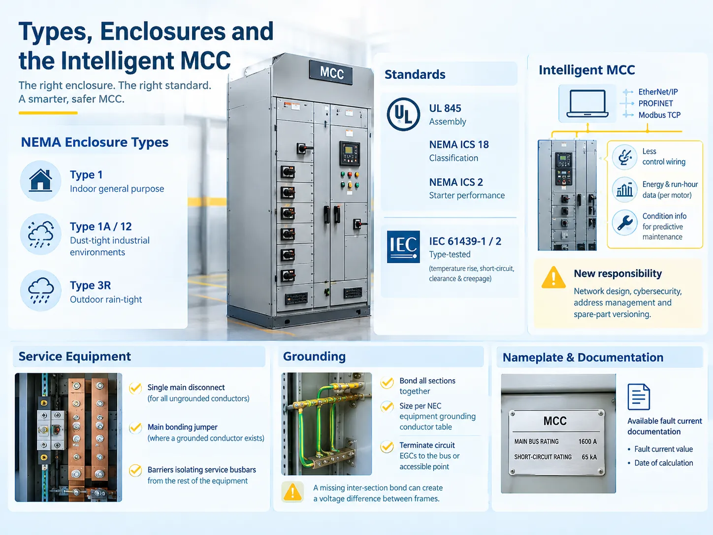
In addition to being categorized based on whether they are fixed or withdrawable, MCCs are classified on the basis of the enclosure they utilize and the standard to which they conform. While electrical ratings are important factors, the NEMA types of enclosure used also play an important role in plant operations that may involve wash down, dust and humidity. This is because failure in an inadequately enclosed assembly takes place due to insulation breakdown resulting from contamination rather than because of a clean electrical fault.
In terms of standards, North America has its own UL 845 and NEMA ICS 18 standards. In addition, the performance of starters is laid out in the NEMA ICS 2 standard. International projects must comply with types that are subjected to IEC 61439-1 and IEC 61439-2 tests to verify temperature rises, short circuit withstand equipment parameters and clearance as well as creepage limits . This shows that a compliant MCC is not a generic qualification since it has to meet a particular standard; therefore, if a bid does not indicate which standard has to be met, it cannot be treated as legitimate.
Intelligent MCCs represent the most significant achievement in the last couple of decades. Wiring every auxiliary contact back to the PLC in the marshalling panel was replaced by the practice where each bucket has a communication module and becomes a part of the plant network. First of all, it allows reducing control cabling significantly; second, it allows getting energy consumption for each motor and run hour data without extra devices; third, it allows obtaining condition data for predictive maintenance instead of reactive maintenance. However, it also leads to new challenges in ensuring that an intelligent MCC works as part of the network system, while electrical maintenance at the same time includes responsibilities for cybersecurity, address management, spare parts versions, etc.
Service equipment, grounding and the code’s requirements
As per Article 430 Part VIII, several conditions should be fulfilled from the very first design meeting. In case if the MCC acts as service equipment, it has to have one main disconnecting device for all ungrounded service conductors/ There should also be a properly sized main bonding device too as per bonding rules in case where a grounded conductor is present, plus barriers establishing an isolation between service busbars and other parts of MCC need to be provided for.
Grounding is usually considered a matter of last resort and it turns out to be the most dangerous when mistakes are done in this respect. All MCC components should be bound into one whole with either a bonding conductor or bus which fall under the given equipment bonding conductor table. It is also necessary to make sure that all grounding cables meet the requirements stated for this bus and the corresponding point. In a situation when sections are not bonded properly, a situation occurs when adjacent MCC frames become influenced by one another having a certain voltage difference. The principles are the same ones that govern every grounded system, and they are worth reviewing at design stage rather than at inspection: the arrangement of transformer and system grounding determines what the MCC’s grounding bus is actually referenced to, and a grounding scheme that is adequate upstream can still leave a motor frame at an unexpected potential if the internal bonding is incomplete.
There are two additional requirements for the nameplate and the drawings. First, there is a requirement for the power bus current rating and the short-circuit rating of the MCC to be marked clearly after the system has been installed. There is a requirement that the MCC fault current should be documented and available to anyone who is permitted to inspect, install, and service the item, along with the date on which the short-circuit was computed.
What feeds an MCC: upstream equipment and rating checks
It is not possible to define an MCC separately, as its rating does not hold significance unless assessed in conjunction with upstream parameters. As a norm, the power source could be a distribution transformer, a main switchboard, or a feeder from a higher voltage substation. Three values should be acquired prior to determining a rating, which includes the supply voltage and configuration, the current consumption by the user, and the prospective short-circuit current at the connection site.
However, it is the last value that creates trouble for projects. An MCC built on the existing site where the transformer has already been changed may deal with the fault level much larger than the designed one; the most common example is a utility renovation that brings more fault power without any major modifications to the production process. That is the reason why providing fault current documentation is required, and why every significant repair operation should contain rating verification.Understanding what the supplying distribution transformer contributes — its impedance, its configuration and its rated capacity — is the starting point for that calculation, because transformer impedance is usually the dominant term in the available fault current at the MCC terminals.
Protection, metering and the role of current transformers
All MCC equipment and numerous large motor buckets depend on current transformers for the detection of actual electrical current flowing. Current transformer reduces the high primary current into some level of its standard secondary current, normally 5 A or 1 A, that can be managed by protective relays and meters.There are three places in an MCC where CTs are applied: on the incoming busbar for overcurrent and earth fault protection; on the large motor starters for differential or thermal protection; and in the measurement panels where the information on energy consumed and energy demand is collected.
Two aspects of design affect the functioning of instrumentation. The first aspect is that the ratio has to be appropriately chosen–the CT has to be above the maximum primary current, while the secondary current should be kept at a level sufficient at normal load for reliable readings. That’s why big motors usually have a CT meant for protection instead of measurements. The second aspect is the total of the secondary load–this is the total resistance of all relays, meters and cables connected to the CT.Selecting a device for this duty is a question of documented accuracy class, burden and short-time thermal rating rather than of physical size, and a representative current transformer range shows how those parameters are published for a specific unit. Current transformers also introduce a rule that no maintenance technician should ever forget: the secondary circuit must never be opened under load, because with no burden the CT develops a dangerous voltage across its own terminals.
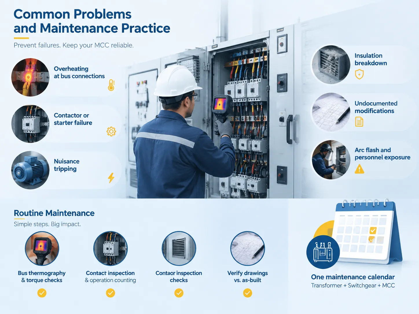
Common problems and maintenance practice
MCC failures are rarely exotic. They cluster into a handful of recurring causes, and most of them are visible on a schedule.
| Problem | Root cause | Mitigation |
|---|---|---|
| Overheating at bus connections | Loose bolted joints, thermal cycling, contamination | Torque checks on a schedule; infrared thermography under load |
| Contactor or starter failure | Contact wear from high operating frequency | Operation counters on intelligent units; planned contact replacement |
| Nuisance tripping | Overload settings incorrect for the actual motor; harmonics from VFDs | Verify settings against nameplate full-load current and service factor |
| Insulation breakdown | Dust, humidity, wash-down ingress, loose debris | Correct enclosure class, gaskets maintained, cleaning programmes |
| Undocumented modifications | Field changes without drawing updates | Controlled drawing revision; verify against as-built at each audit |
| Arc flash and personnel exposure | Work on energised equipment without assessment or PPE | Published incident energy study, boundaries, PPE and procedure |
In fact, the maintenance routine that achieves most of this is one of the simplest types of maintenance, which includes activities such as torque and thermography on the bus, contact inspection and run count for the starters, environmental monitoring of the enclosure and checking that the drawings match the installation. In a plant where the MCC is the single point through which most of the process is powered, that programme belongs on the same calendar as the transformer and switchgear maintenance rather than in a separate silo — a comprehensive transformer maintenance checklist and an MCC inspection schedule share the same logic of scheduled interventions catching slow degradation before it becomes a forced outage.
MCC compared with switchgear, panelboards and VFDs
Meetings tend to confuse four terminologies which mean different things causing a high potential for specification issues.
- Panelboard. It distributes power to combination of circuits with adequate overcurrent protection. No motor starting, no overload protection is present here.
- Switchboard or switchgear. This assembly is intended for power distribution and protection on a larger scale and helps with the distribution of and protection of power.
- MCC. This equipment is built around motor control systems. They provide protection, switching, and overload protection in one bus on modular sections of the assembly.
- VFD. This is just a unit controlling one motor function, which can be located either in MCC or separately. The operation principle of VFD is not identical to that of MCC.
FAQ
What is the main purpose of an MCC?
The goal is to be able to manage, safeguard and monitor several motors from a single central place. In practice, it means connecting all the starters and feeders of a manufacturing sector onto a common power bus in modular constructions. The systems are built in such a way so that the motors may be started, ceased and protected from overheating and short circuit far easier than in case of being wired separately on the site. The second purpose – scalability: instead of reconstruction of the whole system, the necessary capacity can be obtained by adding new segments or attaching sections.
How does an MCC work?
Electricity is supplied via a main device (like a breaker, a lug or a fuse switch) from where it is distributed via a common power bus that spans the assembly. In each section, vertical bars take from this common bus and supply each separately stacked motor control unit with power supply. Each unit (called bucket) is fitted with circuit protection devices, contactor or a drive as well as panel for overload protection. Control wiring provides connection of the units either to pushbuttons or to a plant network (in case of an intelligent MCC).
What are common problems with MCC panels?
Repetitive problems are those due to poorly connected buses that cause hot spots, wearing of contactors in switches driven frequently, incorrect settings of overloads which cause unwanted trips, deterioration of insulation by dirt and moisture, harmonics of VFD-connected motors affecting other loads, and undocumented changes made by technicians that render drawings of equipment useless. Most of the problems are identified by the means of scheduled tests of torque, thermographic inspection, counting of contactors used and environmental checking instead of waiting until failure happens.
What is the difference between a VFD and an MCC?
They function on different levels. An MCC acts as a collection of equipment that supplies power and provides some protection and starting capability for motor drives. Meanwhile, a VFD refers to a single device that modifies one motor speed by varying frequency and voltage. Since drives are commonly mounted in MCC buckets, people tend to mix the two concepts up; however, MCC is the enclosure, bus, and protecting device for the complete set of drives, while the VFD is responsible for controlling one motor. If one completely replaces MCC with VFDs, there will be no proper protection of electric drives together.
References
- NFPA — NFPA 70 National Electrical Code, Article 100 and Article 430 Part VIII (Motor Control Centers)
- NFPA — NFPA 70E: Standard for Electrical Safety in the Workplace
- UL Solutions — UL 845: Motor Control Centers
- NEMA — NEMA ICS 18: Motor Control Centers and NEMA ICS 2: Industrial Control and Systems Controllers
- International Electrotechnical Commission — IEC 61439-1 and IEC 61439-2: Low-Voltage Switchgear and Controlgear Assemblies
- IEEE — IEEE C37.20.7: Guide for Testing Switchgear Rated Up to 52 kV for Internal Arcing Faults
Conclusion
A Motor Control Center (MCC) is where common distribution of electrical energy for the power system ends. The bus is the equipment used for the distribution, while the buckets are used to protect, switch and monitor power distribution. The large metal enclosures and guards have been designed specifically to keep the equipment from exposure, while modern factory networks allow the entire MCC to serve as an operator of power collection. Each manufacturer will have developed a code that includes requirements for bus bracing, phase order, bend and clearance space, bonding at intersections, nameplate marking and fault current documentation. Most manufacturers have three basic decisions to make for all MCCs. First, manufacturers should make the removable MCC component available if the downtime costs are too expensive; second, manufacturers should verify that the fault current rating for each MCC is equal to or greater than the fault currents at the terminals; and finally, manufacturers should provide ongoing monitoring of the engineering documentation while their customer is constructing a facility.