


An engineer of the project in charge of a utility firm is formulating specifications for a main power transformer of the capacity of 40 MVA with a voltage of 132/33 kV that can regulate the distribution bus of 33 kV of the entire region. The design process for the transformer has almost been completed, but on one point the issues were raised at the meetings held: it refers to the on-load tap changer, which got many questions about it. The evaluations of various manufacturers were prepared from the technical point, but their cost may differ by 30%, the maintenance intervals differ 3 times, and service metrics across different designs are unavailable to datasheets. The engineer understands that the utilization of the on-load tap changer is critical to the cost of the operation of the transformer for the period of 30 years.
The goal of this article is to provide the information on the selection of the on-load tap changers of the main power transformer, which will include the tap range, step size, current and step voltage ratings, the differences between resistor and vacuum types, their cost, and specifications needed to be sent to suppliers.
Answer: An on-load tap-changing device is used for adjusting the tap on the winding of a transformer when it is on-load in order to regulate voltage without interruption of supply. For a 10 MVA – 60 MVA unit, the possible setting ranges, respectively, are about ± 8 × 1.25% or ± 6 × 2.5%. The OLTC device is rated for the same through current as the maximum continuous rating of the transformer and has the step voltage equal to the voltage of the winding.

What Is an On-Load Tap Changer?
On-load tap changer (OLTC) is a motor-controlled device found in power transformers that alters the tap connections of the adjustment coil while power remains in use. This is done by increasing or decreasing the taps, therefore changing the turn ratio and the output potential difference, which indicates that OLTC plays a vital role in continuous voltage regulating process under changing load and source conditions.
Being the kind of device that continually makes any operations while the current flows, OLTC is precision instrument, which means that the switching must be done under particular conditions, while switching process must take place thousands of times before OLTC can wear out.
Why a Main Transformer Needs One
Transformers are installed between the transmission system and the distribution system. Both sides of the transformer can experience load fluctuations throughout the day as demand can change, as well as the transmission voltage, which changes due to grid configuration. For instance, when the transformer in question has a capacity of 40 MVA, the impedance drop alone can be anything between 6-12%. Therefore, when it is a question of full load or no-load, the regulations may affect the voltage drop of several percent of the transformer itself. Furthermore, there is a risk that the 33 kV bus can go down by 5-8% below normal voltage, which according to local regulations is not acceptable.
In order to maintain the required voltage variations within an acceptable range, an OLTC is usually combined with the automatic voltage regulator (AVR).
How an OLTC Switches Without Interruption
The OLTC is designed in two phases. The selector finds the new tap point mechanically with the windings already connected via the active tap. Hence, this is where the selector operation is considered as happening with zero current value. After that comes the time of the diverter switch that consequently moves the current from the principle tap to the new tap. The transition impedance is placed between the selector and the diverter switch so the current flowing through is never interrupted.
The design of the resistor diverter operates in such a way that the current travels through one or two transition resistors that are placed in between. The resistance value is selected in such a manner that the current flow is limited to the minimum value during the process.
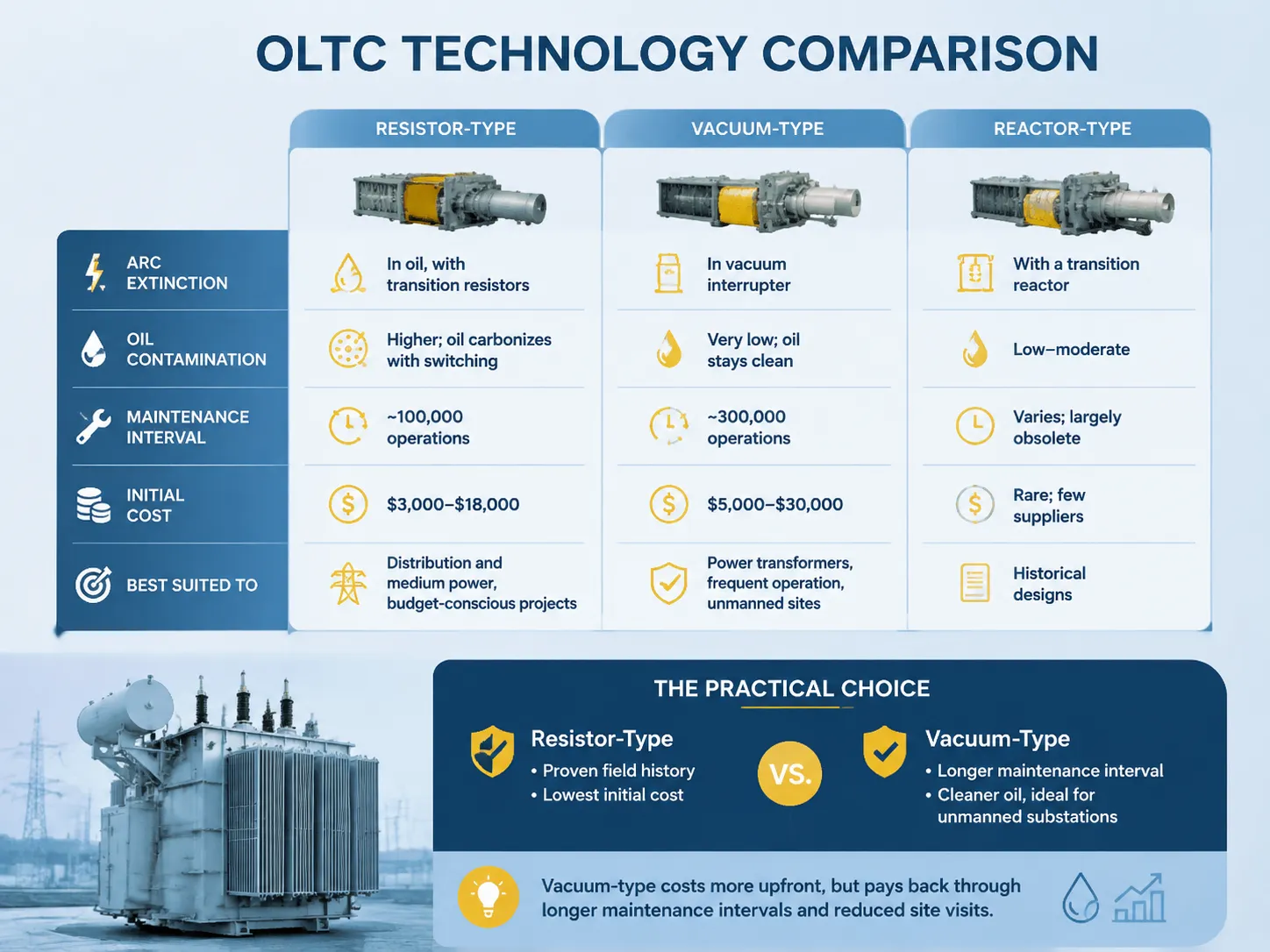
Resistor vs. Vacuum vs. Reactor OLTC
| Characteristic | Resistor-Type OLTC | Vacuum-Type OLTC | Reactor-Type OLTC (legacy) |
|---|---|---|---|
| Arc extinction | In oil, with transition resistors | In vacuum interrupter | With a transition reactor |
| Oil contamination rate | Higher; oil carbonizes with switching | Very low; oil stays clean | Low-moderate |
| Maintenance interval | ~100,000 operations | ~300,000 operations | Varies; largely obsolete |
| Initial cost | $3,000-$18,000 | $5,000-$30,000 | Rare; few suppliers |
| Best suited to | Distribution and medium power, budget-conscious projects | Power transformers, frequent operation, unmanned sites | Historical designs |
When it comes to new main transformers, one can usually choose between resistor or vacuum varieties. The resistor variety has been in use for a long time, and it has the lowest initial cost. The vacuum type, however, costs more in the beginning due to longer maintenance intervals and fewer requirements for oil changes, which can be an important consideration in case of unmanned substations where oil replacement needs site visit and downtime.
Selecting the Tap Range and Step Size
The tap range is a calculation of voltage control. The process consists of several steps:
- Take the actual voltage fluctuation. Measure the voltage of the primary side and the voltage of the bus under full load state; it may vary ±3-8% on an actual grid between light and full load conditions.
- Add the drop in transformer impedance. At full capacity, the regulation of transformers with 10-40 MVA of power reaches 4-8%, and taps should account for both the change of source and internal drop.
- Determine the size of the step. Usually, 1.25% steps are used for large transformers with proper regulation, while smaller transformers work with 2.5% steps.
- Set the range. The ±8×1.25% tap range gives ±10% in 16 steps, while the ±6×2.5% tap range generates ±15% by using 12 steps. For most transformers within the range between 10MVA and 60MVA, the first range is chosen as a standard.
- Think about the AVR which provides a bus voltage with the help of relay in one step with time-lag allowing avoiding hunting, and the number of steps should meet mentioned requirements.
In conclusion, making wrong estimates can lead to consequences: if the range is narrow, transformer will be unable to hold voltage under worst conditions, and if it is too wide, it will mean the necessity of further expenses on OLTC or its regulating winding.
Understanding the Current and Step-Voltage Ratings
| Rating | Meaning | Typical Values for 10-60 MVA |
|---|---|---|
| Rated through-current | Maximum continuous current the OLTC carries | 300-1,250 A (by transformer rating) |
| Rated step voltage | Voltage between adjacent taps | 500-3,000 V per step |
| Rated switching capacity | Product of current × step voltage the diverter can handle | Up to ~1,000 kVA per switching step |
| Operating cycles | Design life in operations | 100,000-300,000+ |
| Standards | Design and type-test basis | IEC 60214-1/-2, IEEE C57.131 |
The through current has to cover the highest continuous current of the transformer plus the overload factor, if applicable, such that for a 20% overload contract the OLTC rating will also have to reflect this. In other words, the step voltage is just as important since high step voltage means much more stress on the diverter than high current with low step voltage; this is verified by the vendor during the switching capacity test.
To help you visualize the relationship, we provide you with the following sizing reference related to the transformer you are specifying.
| Transformer Rating | HV Voltage | Max Continuous Current | Typical OLTC Rating | OLTC Price Range |
|---|---|---|---|---|
| 10 MVA | 66 kV | ~88 A | 100 A, step 500-800 V | $4,000-$12,000 |
| 20 MVA | 110 kV | ~105 A | 125 A, step 800-1,200 V | $6,000-$16,000 |
| 40 MVA | 132 kV | ~175 A | 200 A, step 1,200-1,800 V | $8,000-$22,000 |
| 60 MVA | 220 kV | ~157 A | 200 A, step 1,500-2,500 V | $12,000-$30,000 |
After establishing the ratings, it is essential for the specification to delineate all the requirements using detailed language. At the very least, the RFQ must specify the following items in the clear manner:
- Tap range and steps: must be specified clearly, e.g., ±8×1.25% (17 steps) at the HV winding.
- The rated through-current: what is the maximum continuous current, including overload operation.
- Step voltage: maximum voltage between the taps.
- Type: either a resistor or a vacuum type, turret mount design (head type) or an in-tank unit.
- Motor drive: voltage (110/220 DC or AC), torque limitations, local or remote operation, and AVR interface.
- Monitoring: position display, working hours counter, oil level, and pressure monitoring of OLTC space.
- Standards and type tests: type tests as per IEC 60214-1, plus IEEE C57.131 if the project is based in the North Americas.
- Spares and services: spares and services available from the manufacturers.
There are two most important specification points that are frequently ignored. First, the overload basis, which states that the OLTC should be rated for the transformer’s overload capacity and not only for the rated continuous capacity. Second, the AVR interface and communication protocol, which shows whether the tap changer can become part of the systems of substation automation or will operate on an isolated manual basis.
OLTC by Transformer Size and Duty
- Transformers of lesser power (less than 5 MVA): Oil immersing or oil circulating transformer(OLTC) thus dies not make use of OLTC; on-circuit tapping is done supplemented by regulation at upstream regulators.
- Transformers at the substation level (5 to 60 MVA): The power range for the installation of OLTC; direct caused system based regulators are used along with standard tentative impacts on the regulated bus.
- Step up generator transformers; The OELTC option is rare; regulation being done on the generator or grid level depending on the generating capacity of the generators.
- Transformers at the industrial level (10 to 50 MVA): The OLTC option is also available at this level; however vacuum type of OLTC is chosen where changes in operation are frequent.
- Furnace transformers and rectifier transformers; there is high frequency of tapping operation thus vacuum type of OLTC desired for the operation.
Brands and Price Comparison
| Brand | Origin | OLTC Products | Approx. Price Range |
|---|---|---|---|
| MR Reinhausen | Germany | VACUTAP vacuum and OILTAP resistor series — the global reference | $6,000-$35,000 |
| ABB | Switzerland/Sweden | Complete transformer + OLTC packages | $5,000-$30,000 |
| Siemens | Germany | OLTC for large power transformers | $6,000-$32,000 |
| Hitachi Energy | Switzerland | Power transformer tap changing | $7,000-$35,000 |
| Schneider Electric | France | Distribution-class tap changers | $3,000-$15,000 |
| Jiangsu Subian Electric Power (integrated) | China | Transformers with proven OLTCs coordinated to IEC 60214 | $4,000-$15,000 (as transformer option) |
as MR technology or licensed designs are being used by almost all leading transformers around the world. The VACUTAP series of vacuum tap changers is the one that set the standard for maintenance-free operation. ABB, Siemens, and Hitachi Energy offer their own or partner OLTC technology. The OLTC is usually a named item in the transformer contract and the choice depends on capabilities of the transformer manufacturer and maintenance philosophy of the project. Jiangsu Subian Electric Power is among the manufacturers that install tested OLTCs in their transformers, including the vacuum type for frequent switching. Instead of getting a product that comes with an additional OLTC attached, the buyer gets turn-key assembly covering turret, drive, and AVR as one complete system. Due to the efficient production and pricing policy of Subian, the price range of OLTC transformers is about 40-60% lower as compared to similar offerings of European manufacturers. However, regardless of the brand you choose, always indicate OLTC type in the contract and check the type test certificate.
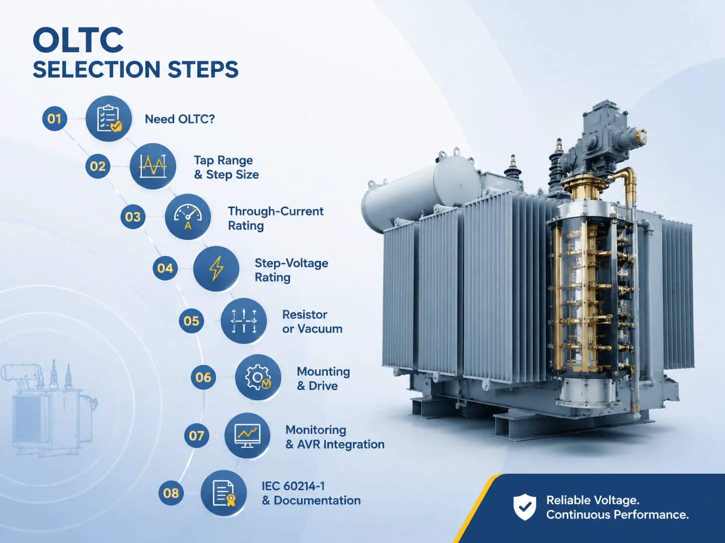
Step-by-Step Selection Procedure
- Assess whether an OLTC is necessary. If the source and load are stable, you may only need manual taps, but in the case of a power transformer, automatic regulation is almost always required.
- Determine the tap step size and range according to the internal regulation of the transformer and the voltage fluctuations.
- Determine the current capacity based on the maximum current available during continuous operation with overloads.
- Double-check the step voltage with the tap-to-tap voltage of the regulating winding.
- Decide whether to use resistors or vacuum based on the budget, domain of application and switching frequency.
- Identify if turret or head mounting is needed and decide about the motor drive, ensuring it bears the correct voltage and controls.
- List the monitoring requirements and the requirements for the integration of the automatic voltage regulator including the position, counter, oil level, and communication protocols.
- Ensure that the certificate of the type-test and process test in accordance with IEC 60214-1 is available, and include the designation of the OLTC in the contract.
Operation, Monitoring, and Maintenance
The need for OLTC servicing is mostly influenced by the kind of OLTC and how often it switches on and off. Recommendations include:
- Track how many times the OLTC has been operated each month. An OLTC used in association with a power transformer may make 1,000-10,000 switches a year; therefore, maintenance intervals should be calculated based on the operating count, rather than based on numbers of years.
- In resistor OLTCs, diverter installation oil should be considered separately from the oil in the main tank, as it gets carbonized during the switching operation and degrades much faster; filter or replace it as per interval specified by the manufacturer (~100,000 switches).
- In vacuum OLTCs, no contamination occurs during operation; hence, intervals may be much longer (~300,000 switches); still, the mechanism and the drive should be checked at every major trip.
- The torque of the motor drive, the position of the AVR relay switch, and the position of the position indicator should be verified every year.
- Monitor temperatures and pressures of the diverter oil; a jump in temperature indicates a fault in the contacts or an abnormal switching process.
- Logging the operation counter is most cost-effective since it changes “make maintenance every five to seven years” into “make maintenance every 100,000 operations,” which means a considerable difference for a busy transformer.
Maintenance required by different designs is drastically different. The two main types of OLTC should be compared based on your expenditures.
| Maintenance Item | Resistor-Type OLTC | Vacuum-Type OLTC |
|---|---|---|
| Diverter oil change interval | ~100,000 operations | ~300,000 operations |
| Oil carbonization rate | Moderate to high | Very low |
| Contact inspection interval | At each oil change | Every 2nd-3rd oil change |
| Motor drive maintenance | Same for both (annual check) | Same for both |
| Estimated 20-year maintenance cost | $8,000-$20,000 | $4,000-$10,000 |
Frequently Asked Questions
How much does an on-load tap changer cost?
What tap range should I specify for my main transformer?
What is the difference between a resistor and a vacuum on-load tap changer?
How often does an OLTC need maintenance?
Can I retrofit an on-load tap changer to an existing transformer?
Rarely and rarely economically. The regulating winding, turret mounting, tank clearances, and cooling must all suit the OLTC, and most fixed-tap transformers were never designed for one. If you need continuous regulation on an existing unit, consider a separate voltage-regulating transformer or a series voltage regulator instead. Otherwise, specify the OLTC at the design stage.
References
- IEC 60214-1 — Tap-Changers, Performance Requirements and Test Methods — The core OLTC standard covering type tests and ratings.
- IEC 60214-2 — Tap-Changers, Application Guide — Selection guidance for ranges, steps, and ratings.
- IEEE C57.131 — Requirements for Load Tap Changers — North American OLTC standard.
- MR Reinhausen — Tap Changer Portal — The leading OLTC manufacturer’s VACUTAP/OILTAP documentation and life-cycle data.
- IEC 60076-1 — Power Transformers, General Requirements — Transformer-level context for tap changer integration and testing.
- ABB Transformers — Reference for transformer and tap changer integration.
Conclusion
Choosing the on-load tap changer for a major transformer is a process that is based on the facts. The variation of voltage and the regulation of transformer determine the range, while transformer’s current and switching capability determine the output. As long as everything is done correctly, the OLTC will perform its functions for many years.
- Calculate the tap range using the actual voltage values and the internal regulation.
- Rate the OLTC according to the overload performance, not just the rating on the plate.
- Opt for vacuum type when frequent switching is involved and there is no man.
- Follow the performance records, log the counter and hold the certificate of the type test attached to the contract.