


An Ethernet data port is basically two wires with a transformer attached to them. In an office environment, the transformer is an “added” step. However, inside of a substation, it’s the only thing preventing a short in the ETH network from causing a catastrophic failure of the switch (which costs more than the short circuit itself). Isolation is the least prominent property of industrial data cabling, but it is also the most critical property.
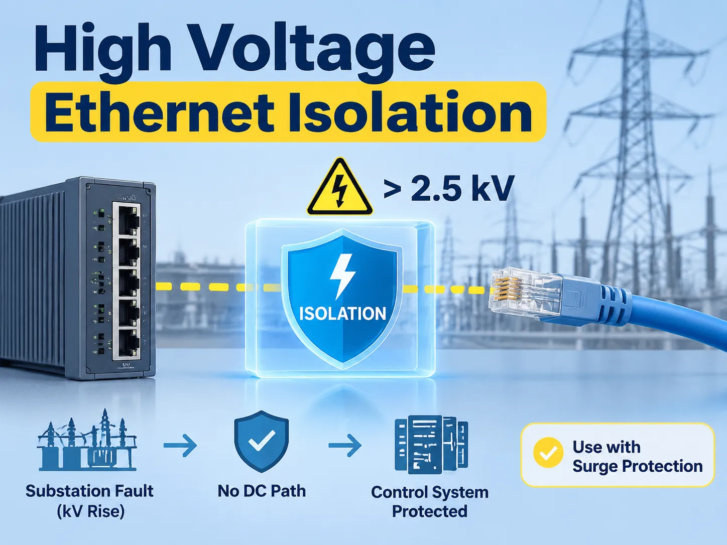
Quick answer: High voltage Ethernet isolation means that the copper port is galvanically separated from the cable. Consequently, there is no DC path from the equipment to the other end. The standard Ethernet magnetics exist at 1.5 kV, while industrial isolators exist at 2.5 kV, whereas reinforced isolators exist above 5 kV or greater. This is extremely important for power installations, due to the ground potential increase of several kilovolts during a fault in a substation (without isolation, an unisolated port can be used as the DC path) to allow the ground potential increase to be transferred towards the control system. Isolation is not the same as surge protection; it only blocks continuous potential differences while the surge devices block transient events. In a proper installation, both isolation and surge protection are used together.
The following sections include information related to what isolation comprises on an Ethernet data cable; why substations are unfriendly environments for copper wiring; ground potential rise calculations; what is contained within the isolation transformer; how the isolation transformers are rated; why isolation vs. surge protection are different; how to decide what option will be the best for your application; where the isolation appears in a power project; an isolation rating comparison; and how our own transformer development fits in.
How a High Voltage Isolator Works on a Data Cable
Isolators separate electrical circuits, permitting no direct line of communication between those two circuits. They accomplish this by either using induction or via light (photo) transmission instead of electron flow through the electrical wires. In some cases, such as an Ethernet port, this isolation barrier takes the form of small pulse transformers (one transformer for each pair of wires) that are placed on the toroidal or pot core, with primary (incoming) and secondary (outgoing) windings separated by insulation.
These transformers allow for two sides to be under different electrical potentials while maintaining isolation between them; this property allows for connection of a data network to equipment located in separate buildings where the earth potential of both buildings may not be the same. One building’s data network may be at 5 kV while the data network of the other building is at zero volts.
The isolation barrier used in power transformers operates on the same principle as the isolation transformers that protect workers and property from electric shock hazards through isolation.
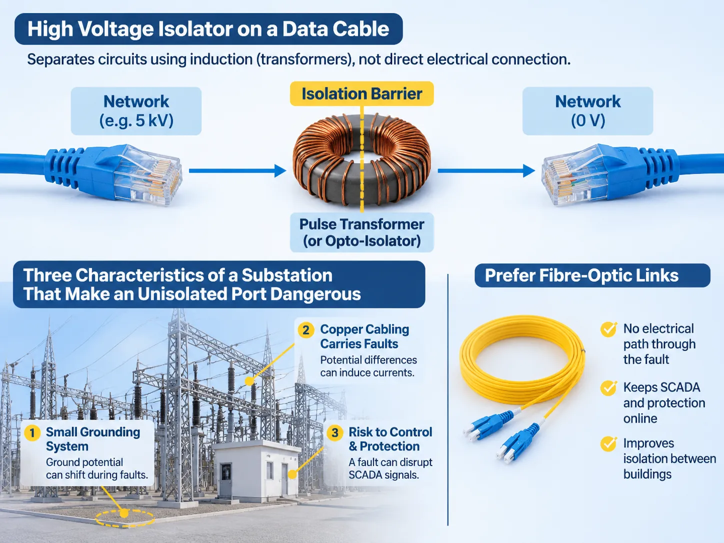
Three Characteristics of a Substation That Make an Unisolated Port Dangerous
One of the key characteristics of substations is the installation of a grounding system that is much smaller than the maximum fault current capability. As such, during a fault condition the grounding system will move with respect to ground potential because of the high fault currents.
Copper installations typically run from the switchyard to control buildings and protection panels, which creates the geometry needed to transform potential differences into currents on cable shields. Substation control and protection systems must continue to function properly through the fault event. If a fault causes a network switch to shut down, it creates an interruption of the SCADA link and protection signals at the time when they are needed most. The failure of a 40-cent transformer that is not equipped for the environment causes this problem.
Substation automation and utility practices promote the use of fibre-optic cabling to connect buildings and isolated domestic copper cabling for local use. This is not just to create a higher-quality signal; it is also so that if a failure occurs inside the substation yard, it will not transmit back through a Cat6 cable to the control room.
Ground Potential Rise in Numbers
When a fault current is injected to ground through a grid, the earth surrounding the fault point increases in potential to earth, based on the amount of current and resistance of the ground (grid). For example, a fault current of 20 kA entering a grid that has a resistance of 0.5 ohm produces a Ground Potential Rise of 10 kV at the fault point, with decay with distance from that point; these figures are typical for a transmission substation, not maximums for larger transmission voltages.
Therefore, the potential difference between two electrical devices located 10 meters apart, during a fault, could be in the kilovolt range, and any conductor connecting these devices would carry current related to the potential difference divided by the impedance of the conductor. An example of a conductor is a cable screen that is bonded at both ends, along with data cables that have an ungrounded port.
In the realm of power, the transformer winding represents the isolation limit, and the power transformer vs. distribution transformer distinction is described in that comparison. In contrast, the data side of things has a similar but smaller sized isolation boundary and the physical phenomenon that creates the need for one also establishes the need for another.
Inside the Ethernet Isolation Transformer
The Ethernet Isolation Transformer is a small pulse transformer used for providing isolation between the data and power sides of an Ethernet cabling system. The transformer has four windings, with each winding corresponding to a pair of wires used in connection to a 1000BASE-T Ethernet connection. The transformer also has a 1:1 turns ratio and a centre tap on the cable side for Power over Ethernet purposes. The transformer permits the passage of the differential signals from the data side of the cabling system (a few hundred millivolts to about two volts peak to peak) while preventing the passage of the common-mode voltage that may otherwise be present on both conductors.
The insulation separating the primary and secondary windings of the transformer is the dielectric barrier, and the thickness of that insulation as well as the creepage distance through the bobbin and potting compound establishes the voltage rating of the transformer isolation. The voltage rating of a component rated for 1.5 kV has undergone a minute’s worth of testing at this voltage; this is separate from the surge voltage and working voltage tests.
There is a limit to how much the transformer blocks. The primary and the secondary windings of the transformer are each separated by a capacitor that typically contains several tens of picofarads of capacitance, and that capacitance will permit the passage of fast transient signals. A surge with a waveform of 1.2/50 microseconds and a rise time of nanoseconds short-circuits the isolation barrier and allows transients to be transferred through the device to the PHY, which is why a clamping device has to be put in front of the isolator.
In addition to providing isolating functions, transformers also act as filters by allowing the signal band to pass through while rejecting all other bands. The addition of common-mode inductors in the magnetics module, and the rise in bit error rate when a replacement is poorly selected, shows that the integrity of the signal depends on an appropriate selection being made.
The construction logic used to develop transformers is similar to that of power transformers. The application of solid insulation, along with controlled creepage distances, serves to define the ratings and not the thickness of the metal enclosure. The approach is implemented at 12 and 24 kV, with a range of dry-type distribution transformers, although additional variables apply to these applications.
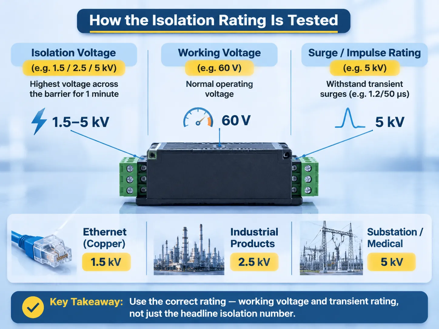
How the Isolation Rating Is Tested
Isolation ratings can be confusing since three numbers appear on a data sheet for each isolator. The isolation voltage test, which is the highest voltage between input and output to the barrier for a specified time (usually one minute at 1.5, 2.5, or 5 kV), is not comparable to, nor can it be interchanged with, the working voltage rating of the barrier. The working voltage rating is the potential difference between the input and output terminals of the barrier that the barrier was designed to withstand under normal operating conditions (much less than the isolation voltage rating). The surge or impulse ratings of a barrier indicate the transient voltages the barrier will withstand without breaking down, and they are expressed in terms of waveform and peak.
The copper Ethernet standard requires an isolation rating of 1,500 V for the copper interface; this is sufficient for most installations in which the equipment is located in the same building and shares the same grounding point. There are industrial products rated 2.5 kV; products for substation or medical applications are rated at 5 kV with reinforced insulation according to the appropriate product safety standards.
For determining a power installation’s rating, only the working voltage and transient rating (60 V working voltage; 5 kV one minute rating) is important; therefore, a product with a 5 kV one-minute rating should only be considered as a local barrier, not a device for interconnecting two buildings that have kilovolt potential differences. The headline number is the most common specification error for this category of products.
Isolation Is Not Surge Protection
Isolation prevents the occurrence of a potential difference over a long period; surge protection protects against transient potentials that last for a very short period of time (microseconds). Isolation and surge protection are fundamentally different and neither may be used as a substitute for the other.
An isolator without surge protection allows transients to pass through the inter-winding capacitance of the isolator causing stress to the PHYs. A surge protector without an isolator provides isolation from the surge, but the continuity of the cable screen connection causes a continuous potential difference to exist at both ends of the cable screen, creating a short-circuit condition at the port. Both surge protection and isolation are necessary when used together in substations; it is important to note that order matters, with surge protection always placed at the cable entry and isolation located behind it in order to prevent a bypass of the isolation barrier. The final piece of equipment needed in both cases is the earth connection.
For isolation to work, both ends of the isolation barrier must have separate earth connections and no cable screens may be connected to both ends of a cable with a screen; if they are, there will be no isolation. If both ends have a bonded screened pair, then the isolator does not perform any function as the screened cable provides the pathway for the isolator to intercept.
Copper, Fibre or Isolated Copper
The selection of copper, fibre, or isolated copper as the medium for a link between two locations that have a potential difference between them is made based on distance, price, and expected voltage difference.
Fibre is the only medium that completely eliminates any conductive pathway because it does not contain any conductive media. However, it has a higher cost per port than either copper medium, requires either a media converter or fibre port at each end, and cannot carry power over the Ethernet. When connecting between a switchyard and a control building, or between buildings, fibre is the most commonly used medium in the utility industry.
Isolated copper is the middle-ground solution that retains the Cat6 cabling and power over Ethernet capabilities of copper cable but adds a rated barrier at the expected voltage difference. Isolated copper is typically the best option when connecting panels that are on different earth bars in the same building or at moderate levels of fault current.
Plain copper is the right medium for connections made within a cabinet or room with a common earth. For all other applications, fibre or isolated copper should be used.
Where the Barrier Appears in a Power Project
The table below describes the setup of the barrier within a project for the distribution of electricity, and it is the version to be included in the design review.
| Link | Barrier | Reason |
|---|---|---|
| Within the protection panel | None beyond the PHY magnetics | Same earth, short run |
| Between panels in a control room | 2.5 kV isolated copper | Different earth bars, shared room |
| Control building to switchyard | Fibre | Ground potential rise during a fault |
| Between two buildings | Fibre, or isolated copper with a surge device | Separate earths, long copper run |
| Substation to control centre | Fibre | Distance plus potential difference |
| Field device to marshalling cabinet | Isolated copper or fibre per the standard | Exposed route, outdoor equipment |
| Camera or access control on a pole | Isolated copper plus surge protection | PoE needed, lightning exposure high |
Of the above, the third row utilizes the “most stringent” requirement that utilities enforce, namely that a copper link from the control building into the yard carries the potential for the yard to earth into the control room, where the protection relays are located, regardless of how many isolation ratings may be assigned to a device/component.
Comparison of Ratings
The table below compares the three product classes to each other. The values shown are typical, not universal. The applicable product safety standard determines the reinforced rating.
| Class | Isolation test | Typical use |
|---|---|---|
| Standard Ethernet magnetics | 1.5 kV for one minute | Office equipment on the same earth; working voltage typically up to a few tens of volts |
| Industrial isolator | 2.5 kV | Panels and machines; different earth bars and medium voltage power systems, with longer conductor runs |
| Reinforced isolator | 5 kV or higher | Substations, medical applications, hazardous areas; most commonly used at system voltages up to and including 1 kV |
When comparing equipment, the voltage rating is not the number to use. A 400 V system may experience a 10 kV differential at a data port during an electrical fault, so the isolation class should be derived from the fault study and not from the nominal voltage. The voltage classification of distribution transformers correlates to the insulation levels assigned to each system voltage, as the data barrier and power barrier are designed to withstand the same fault current.
Where SUBIAN Sits
SUBIAN does not manufacture network isolators; we manufacture the devices that deliver earth rise potential during faults: transformers and substations governing ground potential rise, and hence, the isolation requirements of a data link.
The relationship between our devices and network isolators is much more complex than it appears. A network that incorporates transformers utilising particular vector groups and earthing methods defines the ground potential rise in the control building and will inform the network design. For example, if a transformer incorporates a delta primary and an earthed star secondary, it will have a significantly different ground potential rise profile than a transformer that has a solidly earthed neutral; the isolation rating of the Ethernet port located two rooms away will reflect these differences.
A range of power line transformers has been identified in order to document these earthing decisions, and information specific to dry-type transformers used indoors and outdoors is documented separately due to the difference in earth path.
With a data isolation inquiry, we are able to provide the fault current and the earth connection type; however, we are unable to provide the isolator itself. While we could reference an isolator manufactured by another company, it is much more beneficial to let you know that we do not manufacture the isolator, rather than supplying an uncertain reference of a device.
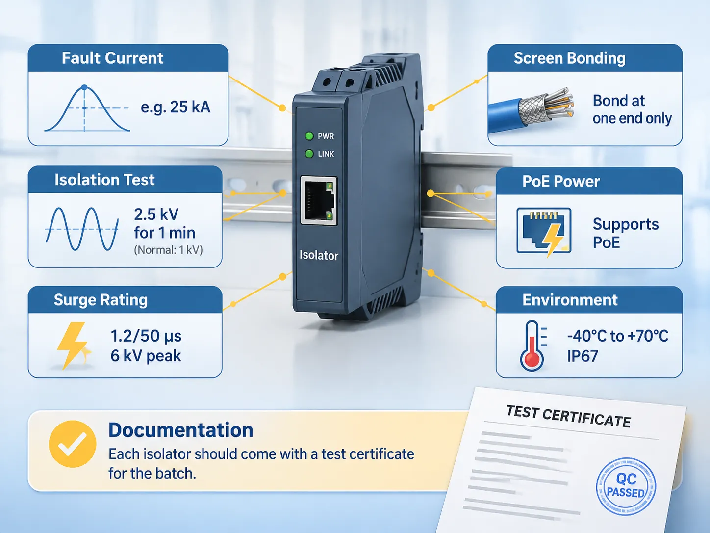
Specification Checklist
The data isolation specification needs to include the following six items:
- The anticipated fault current for the circuit being isolated. This information should be obtained from your fault current study and not from an estimate.
- Isolation testing voltage and duration, with identification of both the isolation test voltage and isolation test duration, as well as the normal working voltage for the equipment being isolated.
- The surge rating of the isolator, with information regarding the waveform and peak values.
- The method of screen bonding for the isolator. If the screen is bonded at both ends, the effectiveness of the isolator is lost.
- The power requirements for Power-over-Ethernet operation, to ensure the isolator does not add to the insertion loss for the power.
- The minimum and maximum ambient temperatures, along with ingress requirements for the enclosure.
When it comes to documentation, each isolator should be sold with a test certificate indicating the rating of each isolator in the same batch as a manufacturer’s statement, and a supplier who cannot provide a test certificate for every unit sold in the batch is selling a product based on an unverified number.
Frequently Asked Questions
What Do We Mean by High Voltage Isolation?
High voltage isolation is the barrier between two electrical circuits that provides a means for energy to pass through but does not provide a conductive path (common reference point) so that each side of the barrier can remain on a different voltage potential. Ethernet uses a pulse transformer designed to work with voltages from 1.5 kV to 5 kV or greater, while in power systems it is a transformer winding that connects the high-voltage and low-voltage networks.
What Is the Function of Ethernet Isolators?
Ethernet isolators produce a galvanic block in the copper data connection that stops current from flowing between the two ends of the cable with a potential difference. They also block ground loops at low frequencies and transfer signal through inductive coupling.
How Much Voltage Can Ethernet Carry?
The actual signal being transmitted is roughly 2 V peak to peak, and Power over Ethernet transmits power voltages of 48 V to 57 V d.c. at a maximum of 90 W with the new standard of the day. The isolation rating is a separate dimension, with standard copper being 1.5 kV, typical industrial devices being 2.5 kV, and heavily constructed reinforced types being rated for 5 kV.
Is There an Ethernet Industry Trend Towards Obsolescence?
That’s a resounding no. Ethernet copper continues to evolve with the introduction of 2.5 Gbps and 5 Gb over existing copper wiring; 10GBASE-T is used in data centre applications, and Single Pair Ethernet is destined for use in industrial field devices. What is changing is that fibre is quickly taking over in the case of there being a potential difference, or for distance, making copper impossible, thus the decision made is related to routing and not the protocols finishing up.
Do Ethernet Isolators Protect Against Lightning Strikes?
To a limited degree; the galvanic isolation blocks continuous ground potential, and the isolator’s capacitance passes fast transients but will not stop a lightning surge, hence it is likely that the isolator must also have a clamping device located at the cable entry. In addition, the isolator must be rated for the allowable potential residual let-through rating of the clamping device.
Is It Acceptable to Use a 2.5 kV Interface Isolator in a Substation?
Yes, in some locations inside control rooms, but for installations between control buildings and utility switch yards, it will be impossible due to the elevated DC potential of utility faults, therefore the correct answer for installation standards is “fibre.” The correct selection will be based upon the results of fault studies as opposed to the product class.
References
- Siemens Energy — Substation Automation and Communication
- Hitachi Energy — Protection, Control and Substation Networks
- Phoenix Contact — Industrial Ethernet and Surge Protection
- UL Solutions — Isolation and Communication Equipment Certification
- Electrical Engineering Portal — Earthing, Ground Potential Rise and Substation Design
Conclusion
An isolator can provide significant protection for data communications, due to the large potential difference caused within a substation. The potential difference is typically defined by kV ratings, rather than volts.
Copper only in a cabinet, fibre if the cable leaves the building, and isolated copper inside buildings where it is required, with each isolated cable screen connected at only one place.